Electrical safety testing and certification is becoming a growing need for manufacturers. Traditionally, safety tests have been performed only for devices powered from the AC mains. However, changes in technology and markets have expanded the need to test and certify many more products. Three examples of growth drivers include the following:
Radio Enabled Devices in the EU– products marketed in the European Union having radio transmitters or receivers require an electrical safety assessment to comply with the Radio Equipment Directive. A safety assessment is required regardless of the power input voltage.
Global Regulations- Many countries outside North America specify safety testing and more are requiring in-country testing and certification.
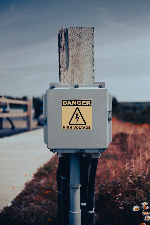
Electric Vehicle Components– High voltage AC and DC on electric vehicles is an electrical safety hazard. Automotive and vehicle engineers must now design for the electrical hazard.
Product Safety and Certifications Day at Elite
To help Elite clients navigate the electrical safety process, Elite partner Product Safety Consulting is scheduled to be on-site at Elite’s Downers Grove lab for Product Safety and Certifications Day on the coming dates.
A safety expert from Product Safety Consulting, Inc (PSC). will be at Elite to answer questions on any electrical safety or mechanical safety matter. This is a one-on-one free consultation with an electrical safety expert.
Clients testing at Elite are encouraged to meet the PSC safety expert while at our lab. Manufacturers not testing at Elite are welcome to come to our lab on Safety Day. Bring your product or technical information and any questions and invite colleagues.
The lifeblood of all services performed at Elite is electrical power. It runs our lab equipment and energizes the products we test.
Given the growing thirst for electric power and the expanding range of DC and AC power conditions, an important first step when preparing to test at Elite is to determine the electric services and specialty power equipment needed for the job. In this article we review the lineup of AC services available to support client testing at Elite’s facilities.
Elite’s Primary Wired AC Power
Each of the three buildings on Elite’s laboratory campus are configured with a range of permanently wired electric power drops. These power connections are used to run clients’ products during testing and to power support equipment like chillers, hydraulic carts, load banks, EV chargers, and specialty power supplies. The most commonly available primary services permanently wired throughout our lab are the following:
480V/60Hz/3-ph (5-Wire WYE) at 60A/phase.
240V/60Hz/3ph (5-Wire Delta) at 30A/phase
208V/60Hz/3ph (5-Wire WYE) at 60A/phase.
120V/60Hz/20A outlets are available at any test and inside our EMC chambers.
Special Purpose AC Wired Power
For applications that need higher voltage, current, or specialty AC power, several Elite’s test stations and chambers are configured for enhanced services. Tests that demand these utilities are scheduled in the vicinity where these specialized power drops are located.
200amps 480V/60Hz/3-ph (5-Wire WYE) is available at 3 Elite drop locations.
Temporary RF filters are configurable at any of our EMC chambers where specialty filtered service is required.
115VAC/400Hz/3-ph, 30amps is available in 7 EMC chamber locations and 6 other lab and environmental test locations.
AC Programmable Power Supplies
When testing demands specialized or unique power conditions, we turn to AC programmable power supplies to meet the need. Elite’s standalone supplies can be moved directly to any of the stations where testing is being performed and provide steady state or transient conditions as specified for the test.
Programmable AC power supplies are required to perform power input testing to industry standards like DO-160 Section 16, MIL-HDBK-704, and IEC 61000-4-11. Each of these specifications define various input AC power conditions to test the unit’s performance when the power anomaly is applied. The tests include changes in frequency, voltage, current, and phase. They also require combinations of interrupts, surges, sags, and other transient conditions that may be present on an AC mains supply.
Elite has an extensive range of specialized AC supplies, but our largest include the following:
AC Programmable Power Supply
1 Phase
3 Phase
Pacific Power 3600AFX (60kW) (4) 15kW Chassis, 1Hz-3kHz
300V/500A
300V/167A
California Instruments CSW5550 (20kW) (4) 5kW Chassis, 40Hz-5kHz
156V/198A 312V/98A
156V/64A 312V/32A
ELGAR SW5250 (5kW) (1) 5kW Chassis, 40Hz-5kHz
156V/39A 312V/20A
156V/14A 312V/7A
Preen AFV-P-600 (600W)
310V/5A
N/A
Preen AFV-P-1250 (1250W)
310V/15A
N/A
Ametek AST3003 (3kW)
200V/15A 400V/2.5A
200V/5A 400V/2.5A
AC Transformers and Variacs
Elite has a series of AC transformers to configure power levels required for specialty applications. These include step-up, step-down, and isolation transformers. In addition, they convert AC power between WYE and Delta arrangements.
70kVA, Pri.(480V) Delta; Sec.(240V) Delta
30kVA, Pri. (208V) Delta; Sec. (480V) WYE
9kVA, Pri. (240V); Sec. (208V)
Elite also has variable AC transformers, called Variacs, that provide fully adjustable AC mains voltage. AC Voltages can be dialed to a specified value as required for testing.
Depending on our clients’ needs and to meet the test specifications defined for the product, Elite can provide an extensive range of AC Mains supply and specialized AC transient test equipment. For more information on Elite’s services, contact an Elite application engineer today to review your project.
Next month, we will describe the types and range of DC power supplies available to test your products. Stay tuned!
High voltage DC on Electric Vehicles (EVs) presents significant design challenges for engineers developing inverters, DC/DC supplies, and other electric powertrain components. Enabling this EV technology are wide band gap semiconductors like Silicon Carbide (SiC) and Gallium Nitride (GaN) which switch faster and can operate at much higher voltages and currents. The inductance associated with these systems as well as the inductance from electric motors produce Ldi/dt kickback voltages and spikes that can damage or affect components connected to HVDC lines. These transients can also couple on the low voltage bus to create issues for downstream vehicle electronics, as well as interfere with nearby radio receivers.
To validate the performance of vehicle electronics and ensure electromagnetic compatibility (EMC), new test standards have been developed for HVDC systems. Many of these methods are prescribed in OEM specifications, but three industry consensus standards have been released for this purpose, they are:
ISO 21498-2
LV 123
ISO 7637-4
This article outlines ISO 7637-4 which addresses emissions and immunity associated with electrical transients for HVDC components. The standard covers passenger and commercial vehicles powered at voltages between 60Vdc and 1500Vdc. It applies to battery electric vehicles, hybrid electric vehicles, and plugin hybrid electric vehicles.
The characteristics of electrical transients on the HVDC bus are complex, but two waveforms have emerged as composite transient immunity models for the EV power bus environment. These conducted pulses are developed in a way to be accurately reproducible using commercially available test equipment.
The first, Pulse A, is a transient burst-set of high frequency (1-10MHz) sinusoidal packets that are applied at amplitudes of up to 100Vp-p. Pulse A represents the ringing transients caused by fast-switching SiC and GaN power MOSFETs.
Pulse B is similarly a sinusoidal based waveform but it covers lower frequency HVDC transients. It is applied to evaluate the effects of sinusoidal waves generated by traction motors and others system motors driven at HVDC. The Pulse B transient is also representative of the disturbance from mains power harmonics that can couple to the vehicle during charging.
Pulse A and Pulse B severity levels, test durations, and performance classifications are listed in Annex A of ISO 7637-4, but as is the case with all industry standards the end use application of the standard is tailored to the equipment and vehicle platform, and in accordance with OEMs specifications.
Additionally, ISO 7637-4 describes a procedure for measuring HVDC conducted transient emissions. Emissions are measured across the HV+ and HV- (line to line) and between HV+ and GND, HV- and GND (line to ground). The key equipment for emissions testing includes a High Voltage Artificial Network (HV-AN) rated for the voltage and current, and a differential probe connected to an oscilloscope. Plots are captured to evaluate the ON-OFF and OFF-ON transients that HV equipment produce on the HVDC lines. Annex B of ISO 7637-4 outlines a framework for quantifying these transients for amplitude, rise-time, durations, etc. The evaluation of the transient characteristics is documented in the report but the actual limits and requirements are generally left to the end user or vehicle OEM to define.
Elite can perform conducted immunity testing per Pulse A and Pulse B and can measure the conducted transient emissions. Specialized equipment used at Elite for this purpose includes shielded high voltage artificial networks (HV-AN), high voltage DC power supplies and loads, along with the pulse generation equipment.
Recently, Elite’s large 1000V/1000A HV test system arrived at its Downers Grove headquarters and awaits commissioning in the high-voltage lab. This equipment is uniquely capable of performing Pulse A and Pulse B immunity transients along with other HVDC transients such as those in ISO 21498-2 and LV123. The related ISO and LV standards include voltage variations, interrupts, and other HVDC conditions that may impact EV performance. More information on these standards and test services is planned in our next blog.
For information about this testing and how Elite can support your HVDC validation, contact Adam Grant at (630) 495-9770 or through our website.
Elite’s Dynamics Lab is among the largest and most capable in North America. The recent expansion with more shakers, larger capacity, and more efficient operation keep our customers on schedule with the flexibility to meet their most demanding requirements. With access to eight shakers, our expert staff delivers complete Vibration and Shock Testing for small electronics and large systems. Our capability has only been limited by the number of accelerometers that could be monitored – until now.
We recently expanded our monitoring capability with our equipment provider, Vibration Research, and are now equipped to monitor up to 68 channels during a single test:
Upgraded six shakers, each with 16 dedicated channels for accelerometer monitoring.
Configured 52 additional channels for on-demand installation on any shaker.
Up to 68 channels available for your test
Now our customers can record more data and save more time in their test programs by:
Employing triaxial accelerometers to record all three axes simultaneously.
Eliminating the need to reposition accelerometers for each axis.
Monitoring more locations and samples concurrently.
New controllers with 16 channels per shaker
As electronics for Automotive, Aerospace, and Military applications grow in complexity with more rigorous durability requirements, Elite is prepared to meet the challenge. If your test plan requires multiple accelerometers, request a quote today to put our new capability to work for you.
In the conclusion of Elite’s transient testing series, Tom Klouda and Tom Braxton review the family of magnetic-field and damped-wave immunity tests. Read more from our transient series in Part 1, Part 2, Part 3 and Part 4.
All transients have a common trait: they’re just passing through. An electrostatic discharge (ESD) is a quick spark that passes in microseconds; an electrical fast transient (EFT) happens in rapid-fire bursts; and voltage surges wash over a device like a sudden wave hitting a boat.
Elite Electronic Engineering’s Tom Klouda has been running and observing these immunity tests for many years and explains that ESD, EFT, and surges are fast, high-energy events. However, there are other transients that aren’t as dramatic but also pose threats to electronic devices. Among those are impulse magnetic fields, damped oscillatory magnetic fields, ring waves in low-voltage cables, and damped oscillatory waves.
The electrical threats are real and there are standards dealing with them all. Elite can help you navigate your way through the transient underbrush and run the immunity tests verifying your product’s ability to shrug them off. This is why they’re called immunity tests: how immune is your product to a real-world disturbance? Here’s a summary of the family of other transient standards and their tests.
Tom goes on to explain how these immunity tests apply and what conditions they’re designed to meet.
Impulse Magnetic Fields Immunity Tests
IEC 61000-4-9 spells out test and measurement techniques for impulse magnetic field immunity. Those fields are used in the manufacture of permanent magnets, therapeutic medical services, and other specialized applications. Like any other electrical event, effects of those impulses can find their way into unrelated equipment. The immunity tests Elite performs under IEC 61000-4-9 measures how well a product continues to function.
The image below shows a typical setup. A combination wave generator (CWG) generates the currents specified in the standard, which are applied to a magnetic-field antenna coil that surrounds the equipment under test (EUT). Depending on the EUT’s shape and size, the test might be repeated with the coil in different positions surrounding the EUT. The magnetic impulses are applied while the EUT is monitored for normal operation.
The images below show the waveform and a typical test setup as defined in the standard. Tests are specified at multiple current levels and for different size induction coils.
Impulse magnetic field immunity test setup in Elite’s laboratory
Magnetic pulses can originate from a variety of sources, including nearby lightning strikes, power plants, and high-voltage substations. The test plan drawn up in concert with the regulatory test engineer will specify the EUT configuration and the specifics of the test application.
Damped Oscillatory Magnetic Fields Immunity Tests
Transient events take many forms, and magnetic fields are no exception. Another version is the damped oscillatory magnetic field which also is a byproduct of power stations and high voltage switching. IEC 61000-4-10 is the standard spelling out test that determines a product’s oscillatory magnetic field immunity.
The figures below show the waveshape and configuration of the oscillatory pulse specified by IEC 61000-4-10. The current level and repetition rate of the waveform will be specified in the test plan. Those choices depend on the EUT’s intended application and the environment where it’s to be installed. The EUT is monitored for any response during the test, following the failure criteria described in the test plan.
Ring Waves Immunity Tests
Yet another flavor of immunity verification for oscillating transients is the ring wave test, described in IEC 61000-4-12. Ring waves are non-repetitive, like the single ring of a bell, hence the name. Peak levels vary from 250 to 4000 volts and have a repetition rate between 1-60 per minute.
The figures below show the waveform specified in IEC 61000-4-12. Note its difference from that of the damped oscillatory wave: it represents the ringing of a single transient event. The image on the right is a schematic drawing of a simple coupling/decoupling network (CDN) that allows the ring wave generator to apply the wave to the EUT’s power lines.
Damped Oscillatory Waves Immunity Tests
In addition to the damped oscillatory field tests described in IEC 61000-4-10, there are damped oscillatory waves propagating along cables. IEC 61000-4-18 defines the test for those. Oscillatory waves are related to the oscillatory fields that result, but the path from interference source to victim is conducted, rather than radiated. For that reason, it requires a different test.
Both slow-damped (100 kHz, 1 MHz) and fast-damped (3 MHz, 10 MHz, 30 MHz) waves are described in the standard, at levels for both common mode and differential mode injection through the CDN. Again, the test plan crafted by the development and test engineers will identify what levels, rates, and modes are appropriate for the EUT’s application.
The images below show the waveform and coupling example as defined in the standard.
Elite’s Tom Klouda and Tom Braxton reviewing the oscillatory field immunity setup
Transients, transients, everywhere
A product intended for use in a harsh environment, like near a power-distribution or generating station, should be tested for the full range of transient immunity. The same immunity tests are applicable for devices used in places surrounded by sudden electrical events like lightning strikes or power switching. Which ones apply to your product? Contact the experts at Elite, and they can help you determine what combination of these immunity tests best fit your application requirements.
Elite’s expertise, timeliness, and trusted results have set a high bar for 65 years. When you have questions on these or any other of the array of tests your product needs, contact Elite for the answers.
Electrostatic Discharges (ESD) are everywhere. We feel them when we reach for a doorknob, a car-door handle, or pull off a sweater. Your electronic products feel them too, and often not in a good way. False displays, logic upsets, or even component damage can result. In Part 4 of Elite’s transient testing series, Tom Klouda and Tom Braxton show how an ESD test is done and why you need to know more about it. Read more from our transient series in Part 1, Part 2, Part 3, and Part 5.
It’s a brisk morning in January and you slide off your coat, settle in the chair next to the equipment bench, and rub your hands together to get the chill off your fingers. Rolling over to the bench, you reach for the power switch on the laptop and – zap! Your arm jerks back and the screen has gone blue. Reboot and hope for the best.
You could change a few details in this story, but we’ve all had this experience. It doesn’t have to be a cold day in January – it could be any time of year in any office or lab. Electrostatic discharge (ESD) has raised its head and bit your finger. ESD also bit the laptop, but the machine doesn’t have an arm to jerk back in response. The laptop was knocked down after taking a punch and is getting back on its feet. You hope to see that no data was corrupted when it comes up again.
Digital devices are especially vulnerable to ESD upsets. The actions described above can build up a charge of 20kV or more between the finger and the surface. The current level is extremely low, but a jolt that size can throw off a device’s internal clock and, in the worst case, damage semiconductor devices.
IEC 61000-4-2, the basic standard for ESD immunity testing, spells out voltage severity levels, test environments, and test procedures. Those specs aim for test repeatability while simulating a condition that is inherently not repeatable. The table below shows the voltage severity levels for two different discharge types, contact and air.
Contact discharge (sometimes called “current injection”) is performed when the tip of the ESD test instrument is touching the test-point surface before the discharge is applied. This simulates the case when there is direct contact between the EUT and the discharge source, as shown by Elite test engineer Brelon Weathersby in the figure to the right:
Elite’s Brelon Weathersby testing the ESD contact-discharge instrument
Air discharge is, as the name implies, a discharge passing from the instrument tip through the air to the test point. The illustration below shows the path of an air discharge.
A third discharge type is indirect, where discharges are applied to a nearby coupling plane. This simulates the condition where the zap occurs in the vicinity of the EUT, creating a momentary RF field that can be induced into the EUT. The illustration below shows the positions of the horizontal coupling plane (HCP) and the vertical coupling plane (VCP). Discharges are applied at the edges of the coupling planes while the EUT is monitored.
ESD behavior is statistical. The equipment under test (EUT) can be zapped in the same place at the same level under the same conditions, and fail every time, half the time, or 1% of the time. That’s why the standard calls for a minimum of ten discharges at each voltage level, negative and positive. If a device is tested a 2kV, 4kV, and 8kV, at both polarities, that would mean 60 discharges at that test point. If the EUT has ten specified test points, there would be 600 discharges applied. It’s easy to see how that number could grow for a more complex EUT.
Any device going through an ESD test needs a test plan showing the EUT’s configuration and test point locations. Test points are chosen based on how likely they will be zapped in actual use. For example, anywhere hands are going to touch, such as control panels and cable connectors, are obvious test points. Conductive surfaces get contact discharges, and non-conductive surfaces (plastic enclosures, painted surfaces, etc.) get air discharges. If an air discharge can’t be generated because the surface is heavily insulated, the non-discharge is noted along with other results.
Maintaining a record of the results is critically important. The test plan will have defined failure criteria stating what is acceptable and not acceptable. If the EUT responds in any way (blinking lights, interruptions, etc.), those are noted for the voltage level and polarity. After many discharges a, pattern might become apparent, and that is useful information for those responsible for the product.
The final report emerging from an ESD test may contain a pass-or-fail determination, but it might be a set of data noting only the responses to the various discharges. Those results are inconclusive and require engineering judgments to be made by the EUT’s responsible engineer. An example of an inconclusive result is a toy that had flickering lights during the ESD test – was that a failure? Maybe not, since it’s not a safety hazard or a loss of function. On the other hand, it could be a hazard for critical displays like fluid levels if ESD causes erratic flashes. These are the types of judgments that are made to determine whether an EUT’s response is actually a failure.
As with any transient phenomenon, the first order of business is understanding the EUT’s failure criteria. The upfront work to craft a test plan will take some time, but it will save both time and uncertainty when the results are known. A thorough ESD test could have predicted the blue-screen reset seen after you slid into your chair and rolled near the bench. Better to know that might happen before your customer is charged to 20kV and finds out the hard way.
Contact Elite for more information on planning and executing your ESD immunity test. You’ll be glad you did.
When lightning strikes, it can cause damaging electrical surges near and far. Are your electronic devices protected from surges on power and signal cables? Elite’s Tom Klouda and Tom Braxton are back with the third installment on transient events and their testing techniques. Read more in Part 1, Part 2, Part 4, and Part 5.
Dark clouds move slowly as the sky changes from blue to purple. Rain begins to fall, and you hear distant thunder rumbling… Crack! Ka-boom! A flash of light and sudden thunder explodes with enough force that you can feel it.
Lightning strikes millions of times around the world and whenever it happens it takes us by surprise. But we share that surprise with our devices. A lightning strike is typically 300 million volts carrying a current between 10,000 and 200,000 amps, and all that energy has to go somewhere. Most of it goes into the ground and startles earthworms, but some is induced into power and signal cables.
If only one-tenth of one percent of that voltage finds its way into local wiring, that’s a 300,000-volt surge being spread around. It’s extremely brief and will quickly diminish, but it’s going to find its way into devices plugged into their power source. While not as dramatic, voltage surges are also produced from major power-system switching and short circuits.
Not to worry though – there’s a test for that. Elite’s Tom Klouda explains how it’s done.
IEC 61000-4-5 Surge Immunity Testing
The IEC 61000-4-5 standard spells out straightforward test procedures for surge immunity. The equipment under test (EUT) is connected via its power cables to a coupling-decoupling network (CDN), which is connected to a combination wave generator that creates the test-surge waveform, shown in the images below. The generator output waveform is defined for both voltage and current.
IEC 61000-4-5 voltage waveform (left) IEC 61000-4-5 current waveform (right)
The levels applied during the test are chosen based on the severity levels appropriate for the EUT. The selection of test levels is shown in the table below.
Because electrical connectivity can be varied (single-phase AC, three-phase AC, DC power source), the form of the CDN is varied as well. The image below shows the connectivity of the CDN is shown in its simplest form. The combination wave generator is capacitively connected to the power lines going to the EUT and the decoupling network prevents the surges from going back into the power source.
Tests are done in configurations of line-to-ground and line-to-line, and in multiple combinations when three-phase power is involved.
The EUT is monitored during the test, with any response noted along with the test levels and operating conditions of the EUT.
Tests are also performed on interconnecting signal lines if the EUT has signal paths that could be affected by induced power surges. IEC 61000-4-5 specifies the CDN connectivity for both shielded and unshielded cables. As an example, the image below shows the configuration for shielded interconnecting cables.
The real value in this test, as for all immunity tests, is in the test plan. The test plan gives the EUT’s description as tested (model, version, connectivity, supporting hardware, etc.) and defines its failure criteria: what should the EUT be doing during the test and what should it not be doing? Any responses in the EUT are noted so that a determination can be made whether the response was acceptable or if it was an actual failure.
At Elite, we’ve tested hundreds of products for surge immunity. We draw on that experience for pre-test advice, compliments of our Regulatory EMC Team Leader, Rick King, NCE, shown in the photo in Elite’s surge-test lab.
Rick reminds clients to confirm the suitability of their transient voltage suppressors (TVS) and to keep in mind that TVS ratings should be chosen based on not only the maximum applied surge levels, (i.e., +/-2kV), but also considering that lower amplitudes of 500V and 1000V are generally required to be tested. Excessive surge energy can enter the EUT if the TVS does not clamp at the lower levels.
Rick also cautions that the lab’s surge coupling networks contain inductors which may create problems for switched-mode and pulse-width modulated (PWM) power supplies. The problem manifests itself as the test item’s inability to power-up during the surge test. Check Annex I of IEC 61000-4-5 for an explanation of this issue or contact Rick King at Elite for more insight.
Lightning and unexpected switching events are going to happen. You can rest assured that with Elite’s deep experience in surge-immunity testing you’ll know how your product is going to behave. Your customers will be much happier when your product continues to work even after those lightning flashes make them flinch.
Contact Elite with your questions on product testing and confirm your compliance before lightning strikes.
Electrical Fast Transients (EFTs) – What they are and how they are tested
Large equipment is switched on and off all the time, and when that happens the power line sputters with bursts of pulses. These are electrical fast transients (EFTs) that can upset an electronic device. Elite’s Tom Klouda and Tom Braxton are back with the second installment on transient events and their testing techniques. Read Part 1 and Part 3, Part 4 and Part 5.
The IT manager at Hypothetical Tech’s branch location is talking with his colleague at the home office:
“We settled into that new office park. It’s the space next to the campus HVAC plant. Lots of room, and we’re in business! Well, except Tuesday — four terminals crashed and we had to reboot. Then on Friday it happened again, and we checked for lost data. While we were down the folks in the HVAC plant came by to visit while they waited for their system to start up. Nice guys.”
Does any of this sound familiar? It’s what can happen when digital systems are hit with an electrical fast transient (EFT). That HVAC plant next door had large blowers with hefty startup currents. When the switch closes and the motor commutators start connecting, voltage spikes flash through the building’s wires.
High-current motors are a common EFT source, as are the switch contacts themselves. The sudden voltage change is like striking a bell – a series of bursts, each of which linger until the energy has run out.
What do bursts look like?
Think of an old-school desk telephone with a mechanical bell. The bell rings in repeating bursts and generates an acoustic waveform like that shown below.
In an EFT event, the current from the sudden surge splatters through the conductors’ natural resonance and sends bursts flowing into devices connected to the common power wiring. EFT bursts are electrical, not acoustic, but the pattern is similar. The EFT voltage bursts resemble the acoustic bursts of the ringing bell.
What is EFT?
The International Electrotechnical Commission (IEC) characterizes EFT bursts in standard 61000-4-4. Like most standards, the electrical specifications are tightly defined.
The staccato bursts of voltage in the field are like snowflakes: they are never quite the same twice. But they do have common characteristics that are standardized to allow repeatable testing. Each individual pulse has a waveform defined in IEC 61000-4-4, shown in the image below:
A series of these pulses are sent into the power line at a designated repetition rate, forming a burst of a specified duration, which is then repeated at 300ms intervals and resemble the telephone-bell acoustic pulses shown above:
The voltage levels and repetition rates of the bursts are set based on the severity level appropriate for the equipment under test (EUT) and are run for a minimum of one minute.
As with any immunity test, a test plan is needed to assure the product is receiving a realistic approximation of what happens in its intended environment. The test plan would include a description of the product, its configuration during the test (connecting equipment, cabling, active software, etc.), and the criteria for failure conditions.
The test plan and the description of failure criteria are important. During the application of the bursts, the EUT is monitored for correct operation. If the EUT reacts to the bursts, is it a failure or a benign response? For example, flickering display lamps may not count as a failure for some consumer products but may be critical for medical equipment. Whatever could be regarded as a failure needs to be described in the test plan.
Not all responses can be known ahead of time, so someone familiar with the EUT should be present during the test to watch for anything unusual. Any response should be documented for later analysis. It’s obviously important for the EUT’s designer to know how the product responds to these kinds of transients.
Applying the burst to the equipment under test (EUT)
The burst defined in IEC 61000-4-4 is applied to the EUT through its external cables. The EUT’s vulnerability is tested by connecting the burst generator to the power cables through a coupling-decoupling network (CDN).
The image below shows a schematic view how it’s done inside the CDN. The right-hand side of the image represents the coupling section injecting the burst directly into the power lines. The left-hand side is the decoupling section preventing the burst from propagating into the external power grid. The photo shows the CDN application in Elite’s laboratory.
Photo showing EFT test using a CDN in Elite’s lab.
The next image shows how the burst is applied to signal cables in a tabletop configuration. The cables are laid inside a coupling clamp that capacitively applies the burst. The photograph shows a typical configuration.
Drawing showing EFT test with coupling clamp.
Photo showing coupling clamp during an EFT test in the lab.
These tests are best done in a laboratory, but if that’s not practical the test can be done in situ (on site in its installed condition). The IEC 61000-4-4 standard shows alternative test configurations that can be applied.
The EUT is monitored for normal operation for the duration of the test and any responses are recorded. The failure criteria defined in the test plan determines if the responses are failures. If not, the EUT has passed.
If your product is to carry the CE Mark so that it is eligible for sale in the European Union, IEC 61000-4-4 is among the suite of standards it needs to meet. Be aware of how your devices respond to an EFT burst. Then if your customers install your equipment near some heavy machinery, you’ll have fewer things to worry about.
Contact us today to get more information and schedule your product’s transient tests to achieve CE Mark compliance, along with the range of FCC, ISED, and others your product needs. When your customers hear the big motors start up next to their site, they won’t spend time recovering lost data and you won’t spend time trying to find out why.
The weeks and months pass quickly this time of year. The days are transient things, popping on the calendar and vanishing before we notice.
This is the first of our new series with Elite’s Tom Klouda and Tom Braxton. Stay tuned for more transient talk in future blogs. Read Part 2, Part 3, Part 4 and Part 5.
Transient events are everywhere, including the space around your product. Can your device tolerate a voltage surge? An electrical fast transient? An electrostatic discharge? A magnetic impulse? The only way to find out is to test it, and your product will need to navigate that test. You’ll need an experienced guide to get you there. The International Electrotechnical Commission (IEC) provides the standards, and Elite Electronic Engineering is the guide you need to lead you through.
What are transients and where do they come from?
A transient is a short-duration pulse brought about by stored energy or a disruption in current flow. Anyone who has experienced electrostatic discharge (ESD) when pulling off a sweater during low humidity then reached for a metal doorknob has dealt with transients. The ESD between the metal surface and the finger is a stored-energy phenomenon.
Voltage surges on power lines are examples of a transient brought on by current-flow disruption. When an electrical contact is interrupted by opening or closing, voltage arcs and mechanical bouncing of the contacts create random pulses. There will be uncontrolled transients that depend on several factors: the contact type, the voltage and current levels, whether current is AC or DC, and the conductors’ geometry. Devices in line or adjacent to the source of those transients are all vulnerable to disruption or damage. The figure below gives a simple illustration of a switch contact being closed and the arcs that would bring about transient pulses.
Illustration showing contact closure and generation of transient pulses
These transients can cause digital logic upsets that appear as process interruptions or corrupted data. Some transients can cause actual damage, like that shown in the picture below. Logic upsets are more common and can range from a simple annoyance to a critical malfunction and can be minimized with error-correcting software. Component damage is clearly a larger concern as it results in a costly repair or replacement.
Example of transient surge damage
Transients can be radiated or conducted, or sometimes both. For example, energizing a high-current device will almost certainly generate a series of electrical fast transients (EFT) on the power circuit, which will propagate to other devices drawing energy through power cables in that building. In addition, that event will create a momentary radiated field that can be induced into other conductors or directly into nearby devices.
Though transients are uncontrolled when they occur, repeatable test procedures are in place that offer confidence in your product’s ability to operate normally when transients happen.
How are products tested for transient immunity?
There are different types of transients and different types of products. The IEC standards and guidelines establish product categories and test procedures for a wide range of transient phenomena. For example, IEC 61000-4-2 addresses ESD immunity, laying out test procedures and severity-level choices that can be chosen depending on the product type and its intended environment. The figure below shows a typical application of the test.
Example of an ESD test being performed on a product and the range of voltage levels given in IEC 61000-4-2
Similarly, voltage surges are covered in IEC 61000-4-5, which spells out test procedures that are effective in predicting a product’s ability to withstand lightning surges and other sudden voltage spikes. Voltage levels are chosen based on the product’s category and intended environment.
Voltage waveform applied in an IEC 61000-4-5 surge test, and the specified voltage levels
Your product will be subjected to a variety of transient events: power surges and ESD, as shown above, but also noise bursts, voltage dips, and magnetic pulses, among others, all identified in the IEC 61000-4 series of standards.
Your product’s application and intended environment will determine which tests to apply and at what levels. The experts at Elite Electronic Engineering can explain the tests and guide you through the necessary steps toward verification.
Be sure to follow the Elite Insider Newsletter in the coming months. Those newsletters will review in detail the transient types, the standards that define and characterize them, and the tests that are performed to evaluate the immunity of your product. Continue with Part 2 and Part 3, Part 4 and Part 5.
Elite Electronic Engineering draws on 65 years of experience in testing products like yours and brings its expertise and evaluation skill to answer your questions. We’ll see the days grow shorter this season and become more transient as they go by. Verify that your product can also see transients go by — Contact Elite to find out how.
Electromagnetic Compatibility (EMC) tests require the use of specialized and costly pieces of electronic equipment. The electronic equipment must perform the measurements accurately and efficiently. A process used to acquire equipment at Elite Electronic Engineering, Inc. that has been successful is a collaborative effort between Elite, our customers, and the equipment manufacturers.
The process starts by identifying a need for the equipment. The need can be identified from schedule bottlenecks, missed opportunities, operation safety concerns, or functionality. Once the need is identified, various manufacturers of the test equipment are researched. In our research, we consider the equipment’s features, cost, warranties, and service. Often, equipment on the market does not have the required features to meet our customer’s needs. This situation is where Elite’s personnel provide valuable insights. Our customers and equipment manufacturers know everything about the design of their equipment.
However, Elite is in the unique position of knowing how to test our customer’s equipment and how to use the manufacturer’s test equipment. Knowing our customer’s needs, Elite’s personnel work closely with the manufacturer to design equipment that accurately and efficiently performs the tests. This collaborative relationship has benefited everyone involved. The EMC test industry also benefits because now the equipment Elite helped to design is available to everyone.
Tom conducting an internal equipment training session in August.
Do you have any questions about choosing EMC Test Equipment, Lightning Testing, or other related topics? Please share your comments or questions below and this week’s expert, Tom Klouda, will get back to you as soon as possible.


