In January 2020, the Brexit withdrawal triggered new laws and regulations for the United Kingdom. Among them were changes to the conformity assessment process for manufactured goods.
The UK, while a member of the European Union, used the CE Mark as their compliance label covering a wide range of products. With Brexit, the UKCA Mark became the new compliance label for the UK countries of England, Scotland, and Wales.
A transition period was set allowing either the CE or UKCA Mark, but only up to January 1, 2024. However, the UK Government recently announced an indefinite extension to this date, which means the CE Mark will continue to be recognized as an accepted regulatory compliance label. This revised policy applies to 18 UK Department for Business and Trade (DBT) regulations.
The extension provides businesses the choice to use either the UKCA or CE approach to sell products in Great Britain. Many Elite Regulatory EMC Testing clients are affected by this change since the UK EMC regulations for Radio Equipment, Low Voltage Electrical Equipment, and Machinery regulations are part of the 18 DBT requirements covered by this indefinite extension.
You can also discuss these changes in-person with Elite and our global regulatory compliance partner Global Validity at the Automotive Testing Expo on October 24, 25 & 26, 2023. The event is held at the Suburban Collection Showplace, Novi, Michigan.
Visit booths 15042 and 15038 and talk to our experts in person.
Corrosion is an electrochemical oxidizing process that affects the appearance and performance of metals and other materials. For electronic equipment, exposure to even mildly corrosive environments can create a range of problems that go beyond appearance. These include connector interface and contacts discontinuities, which then manifest as intermittent electrical faults or permanent failures. Salty atmospheres accelerate conductive bridging across circuit board traces and cause electrical shorts. Corrosion can also weaken structural elements and fasteners and degrade the adhesion of paints, films, and coatings.
To evaluate electrical device and other items for resilience to corrosive and oxidizing environments, standardized tests are available to perform the assessment. The most common tests include exposing products to a 100% saturated humid environment consisting of a steady state 5% NaCl salt fog. Typical standards for these environments include ASTM B117, MIL-STD-810 Method 509, and IEC 60068-2-11. These tests run continuously for a specified period of hours, or in the case of MIL-810 the exposure is applied in one or more cycles of in-chamber fogging then out for a drying period.
An even more aggressive test that accelerates corrosion is IEC 60068-2-52. This standard cycles through a sequence of conditions starting with a salt fog wetted period, followed by damp humidity then dry conditions, and then repeated for multiple cycles. The cyclic nature of fog exposure followed by humid and dry periods is effective at reproducing the effects of natural environments and can accelerate the corrosion mechanism. Because of its robust nature, IEC 60068-2-52 is adopted as the corrosion and salt fog validation standard for many passenger car and commercial vehicle OEMs.
Elite’s Cyclic Salt Mist Chamber
Elite’s new Cyclic Corrosion Test Chamber is uniquely designed to run the IEC 60068-2-52 test and complete it efficiently and accurately. Since this test includes cycles that can last up to 60 days or more, an automated chamber such as Elite’s is critical for time and cost savings.
The chamber internal dimensions are 76″ long x 45″ deep to support testing of larger assemblies or testing of multiple samples. It is also configurable for a wide range of common corrosion tests like ASTM B117, ASTM G85, and SAE J2334. In addition, specialty corrosion tests are supported including for Copper-Accelerated Acetic Acid Salt Spray (CASS) and Acetic Acid Salt Spray (AASS).
For more information on this new service and our chamber capabilities, contact Elite today to discuss your salt fog and cyclic corrosion testing requirements.
Elite has taken delivery of a new vibration table to its lineup of mechanical vibe and shock test equipment. The arrival of the IMV Model A74 improves scheduling start-date options and provides an optimized configuration for Elite clients.
The A74 has a frequency range of 0-2600 Hz and a maximum displacement of 3” peak-to-peak. It can drive Vibration and Shock Testing with 16,500 force-pound capacity with a 36” x 36” slip plate. For combined temperature-vibration testing, it can also be configured with a thermal chamber to run at temperature extremes. It also operates in an energy-saving power mode to improve operational costs. This new system’s power, range, and versatility make it ideal for automotive, aerospace, and module-level testing.
This system will be mated to a Vibration Research control system to provide setup and monitoring of testing functions and data-reporting for test-report analysis.
The new vibration system was delivered to Elite in components in late July and is now operational and running tests.
Elite takes delivery of the new IMV A74 vibration testing system
Mechanical environments for manufacturers’ products can be severe, making it critical to test for susceptibility to vibration and shock. Contact Elite today and find out how we can put its state-of-the-art testing capability to work for your products.
Electric vehicles have new high voltage components and new test requirements. Elite is excited to announce that new, broader test capabilities are coming soon to Elite’s one-location campus in Downers Grove, Illinois. This new equipment will make Elite the only testing lab in North America to offer complete high-power testing to new electric vehicle (EV) components.
The rapidly evolving automotive technology calls for the latest and most complete testing capabilities. Elite is investing in the tools that offer those capabilities to its customers.
Responding to the automotive industry’s movement toward high-voltage electric vehicle (EV) modules, Elite is equipping its lab with AMETEK-CTS PowerWave 250 power sources capable of testing components connected to an EV’s high voltage (HV) bus. The PowerWave is designed to test high voltage components up to 1500 VDC, such as electric drives, batteries, and auxiliary components.
Elite’s lab will be able to provide up to 1500 VDC and 500 kVA/kW for EV high voltage component testing, along with 100% source/sink and power recovery.
Increased Vibration Testing Capacity
But that’s not all. Elite is also taking delivery on a vibration test system that further expands Elite’s industry-leading Vibration and Shock Testing lab. The IMV A74 test system has a frequency range of 0-2600 Hz at a maximum displacement of 3” peak-to-peak. With a maximum force-pound capacity of 16,500 and a 36” x 36” slip plate, the new table’s power and range makes it ideal for new automotive component testing.
Contact Elite to find out how these new tools can be put to work for your EV and its high voltage components.
Vehicle fires are frightening events. They result in about 300 deaths annually, according to the National Highway Traffic Safety Administration. With over 282 million vehicles registered in the US, fire safety standards and requirements are fundamental to the automotive industry.
Federal Motor Vehicle Safety Standard (FMVSS) 302, “Flammability of Interior Materials,” dates from 1971. Drawing from practices developed by the Society of Automotive Engineers (SAE), the goal is to minimize the horizontal burn rate to allow more time for a vehicle’s occupants to evacuate.
Material testing is key to this effort. Resistance to combustion and flammability is an imperative to assure the safety of components in automotive and aerospace products. Panels, wiring, subcircuits, plastics, and fabrics are just a few of the materials that make up these components.
In addition to FMVSS 302, Elite is accredited to perform flammability and burn rate tests in accordance with RTCA DO-160, and MIL-STD-202, giving us deep experience with this type of testing.
FMVSS 302 Vehicle-Interior Flammability Testing
FMVSS 302 is concerned with burn resistance of the components used in passenger vehicle occupant compartments. Components are defined to include these:
Seat cushions, seat backs, and head restraints
Seat belts
Headliners
Armrests
Convertible tops
Trim panels
Floor coverings
Visors, curtains, and shades
Wheel housing and engine compartment covers
Any other interior material
The requirements apply to any material that is within 13 mm of the interior compartment air space, which is defined as the interior space normally containing “refreshable” air. Also, any material that adheres to another material in the compartment is tested together as a composite.
Having identified the materials to be tested, a rectangular “coupon” of the material measuring 102 mm x 356 mm is provided. If the material is thicker than 13 mm, it is cut to 13 mm measured from the surface that would be closest to the vehicle’s occupant.
The sample is mounted in a U-shaped frame and placed horizontally in the center of the flame-testing chamber. A 10 mm-diameter Bunsen burner is set in the chamber, with natural gas adjusted so that the flame is 38 mm in height. The burner’s air inlet is closed when the flame height is set to ensure that only gas is feeding the flame.
The burner is positioned so that its tip is 19 mm below the center of the test sample’s open end. The sample is exposed to the flame for 15 seconds. The progress of the sample’s burn is timed, beginning when the burn reaches 38 mm from the sample’s open end, until it reaches a point 38 mm from the clamped, or far end, of the sample. If the burn stops before reaching that point, the time is recorded.
The sample’s burn rate “B” is then calculated: B = 60 x (D/T),
Where:
B = burn rate in mm/minute
D – length (mm) of the travel of the flame
T = time (seconds) for the burn to travel D mm
A sample passes the test if it has stopped burning before 60 seconds from the start of timing and has not burned more than 51 mm from the point where the burning was started.
Testing Your Component
Any fire near people is dangerous, and fires inside vehicles are especially so. These tests help provide a measure of safety to those inside a vehicle if an interior component ignites. Contact the flammability experts at Elite to find out how to prepare your material for testing.
Go to the gas station and fill your tank, then go inside for coffee. On the sales counter, buy a bottle of washer fluid, then back outside add it to your car’s fluid tank. Within those few minutes you exposed yourself to benzene in the gasoline, formaldehyde from the counter’s pressboard, and methanol from the washer fluid.
The amounts were extremely small, and the time was brief, but it was still chemical exposure. In contrast, a device or product is continuously exposed to chemicals, some more than others, and the effects vary depending on the product’s construction and its operating environment.
Elite Electronic Engineering has been performing chemical exposure tests on products for many years. Standards exist for chemical exposure:
Radio Technical Commission for Aeronautics (RTCA) DO-160
MIL-STD-810, which apply to both aircraft and ground vehicles
SAE 1455 and ISO 16750-5, which focus on road vehicles
Elite’s Nick De Pasion and John Gondek have long experience with chemical exposure testing. It’s not unusual for a customer to inquire about a chemical exposure test and not be certain of what they need to help Elite’s staff craft a test plan. While the standards give test methods and define the contaminants to be used in a test, the interpretation of the actual test is highly dependent on the test sample (or samples) and the customer’s understanding of its intended environment.
Customers need to know that storage and disposal of contaminant fluids is a logistical concern in planning the test. Depending on how much is needed for the series of exposure tests, their storage and shelf life need to be factored into the plan. Some contaminants necessary for the test require licensing to obtain it and to store it, and costs can grow quickly.
Nick and John have come up with a list of things to know if your product will need a chemical exposure test. Keep these in mind if you’re planning to have your product tested to one the appliable standards.
Chemical-exposure engineers Nick De Pasion and John Gondek
Chemical Exposure Test Checklist
Do not assume what type of test will be needed. Discuss test details like the choice of contaminant, the method of application, and the temperature level with the Elite experts. The choices will be made depending on the product’s material and its intended use.
Know what standard applies to your product. This is well understood in most cases, but the device and its application may cause multiple standards to apply.
Know what material needs to be tested. Most products are assembled from a combination of metal, plastic, vinyl, ceramic, or other materials, all of which have different responses to different contaminants.
Determine how many samples of the product will be tested. If there are multiple samples, will they receive the same test or will different exposure tests be applied to different samples?
Know how the end customer will use the product. If it’s exposed to water, is it sprayed like rain, or soaked as in submersion? If it’s likely to have significant exposure to fumes, what kind of fumes and for how long? These questions are fundamental to devising a meaningful test plan.
Know what results you’re looking for. Should the product be complete impervious to contaminants, or is cosmetic damage tolerable if it functions correctly? How much cosmetic damage is acceptable?
Be aware of safety issues with the type of contaminant to be applied in the test. A discussion with an expert at Elite will help resolve that question.
Determine how is the contaminant to be applied. How many times will it be applied, and is there a cleaning procedure needed between applications? The standard will show how to do it, but the choice of whether to spray, brush, or wipe the contaminant on the product surface will depend on the product’s construction and its likely environment.
Determine if the whole product sample to be exposed to the contaminant, or only sections.
Determine if the contaminant fluids are to be applied at the same time or as part of separate tests.
Determine if the test fluids for the test are readily available. Some are costly and difficult to obtain. Elite’s experts will work with you toward the best answer to that question.
As always, contact the experts at Elite with these questions and others that are specific to your product. Chemical exposure testing is well understood and is defined by the standards, but each test is as unique as your product. Elite has seen them, and knows what you’ll need to know.
What do cars, trucks, boats, airplanes, lampposts, and socket wrenches all have in common? At first glance, it wouldn’t seem to be much. But all are exposed to corrosive effects of weather, water, pollutants, and more. The basic corrosion-resistance evaluation of material and its coating is salt fog testing.
Corrosion costs many millions of dollars annually and left unchecked can cause structural failure. Salt fog testing allows new designs and coatings to be scrutinized in a controlled environment and is useful to determine the corrosion resistance of different metals and finishes.
Elite performs salt fog tests as part of its suite of climatic tests. A product and its exposed surfaces need to go through a gauntlet to meet the necessary qualities to get to market— of these, salt fog is the primary test. Other tests, including dust, chemical fluids, gravel, water, pressure variations, and explosive environments are available for products needing to meet specific requirements.
Kyle Thompson and Chuck Thompson checking a salt fog test at Elite’s lab.
Salt fog is a type of accelerated corrosion test that is performed to assess the comparative corrosion resistance of certain materials when exposed to salt fog or salt spray at increased temperature levels. Automotive and aerospace applications make extensive use of salt fog testing to confirm the integrity of materials and coatings. Elite’s long experience in salt fog testing gives its experts the tools to help you navigate what can be a difficult process. Standards for salt fog testing include:
American Society for Testing and Materials (ASTM) B117
Of these, ASTM B117 and MIL-STD-810 are the most common. They call for temperature maintained at 35⁰C in the test chamber as a mixture of 5% sodium chloride in ASTM D1193 Type IV water is introduced at specific air pressures. Exposure is done in 24-hour blocks, with the number of repetitions determined by the type of material and its intended environment.
Effects of long-term salt exposure on exposed surfaces.
Planning a Salt Fog Test
The test plan developed by the customer and the Elite engineer will specify the duration of the testing and the pass/fail criteria used to determine the test’s result.
Small Cabinet 42”w x 30”d x 36” h, available for SO2 tests in ASTM G85 tests
Large Cabinet, available for non-SO2 tests, 93″w x 48”d x 48” h
The test plan will specify the sample or samples to be tested, the specific standard to be applied, the duration of the test, and the pass/fail criteria to be used at the completion of the test.
Among the parameters that can be observed in the test sample during the salt fog test:
The permeability of seals
The amount of corrosion creepage when a coated surface is scratched, per ASTM D1654
The level of coating adhesion, per ASTM D3359
The degree of surface blistering, per ASTM D714
The degree of material rusting, per ASTM D610
How Does Salt Fog Testing Correlate to the Real World?
Correlation between a real-world environment and salt fog testing in a lab is difficult. Materials and coatings can vary widely. Actual outdoor environments are even more variable at any time of day or in any environment.
The materials industry has chosen the salt fog test as a useful baseline that gives an indication of a corrosion vulnerability. The salt fog test is widely used because of its repeatability.
Corrosion is going to happen in a product’s life. Contact the experts at Elite to find out how to apply the salt fog test to your product.
Did you ever wonder how it is that the labels and lettering on aircraft are still readable after thousands of hours in all weather, temperatures, and altitudes? Or how even though they are grimy, your car and its engine compartment don’t just peel away?
Exposure to the real world’s fluids, gases, and extremes is unavoidable, but it can be understood and measured. Equipment expected to perform in harsh environments rely on chemical exposure testing to show how it will hold up in those conditions.
Nick DePasion leads Elite’s chemical exposure testing program. “The aviation and automotive industry are most often in need of these tests,” he said. “There are standards that have to be met, depending on the industry and the product’s environment, but in addition manufacturers have their own requirements.”
Nick’s years at Elite has given him an appreciation of the nuances of chemical exposure. “Labels on equipment surfaces are a big part of those tests,” he explained. “The customer normally brings in a piece of equipment with the label or lettering applied. The sample is exposed typically to a full day of testing, with sixteen hours of exposure followed by eight hours off, with temperatures defined for each phase.” Times and temperatures can vary depending on the material, the standard, and the manufacturer’s needs.
Elite chemical test expert Nick DePasion
The standards for chemical testing are based on the application. MIL-STD-810 and RTCA-DO160 apply to aviation equipment, while SAE 1455 and ISO 16750-5 apply to automotive components. Each test is different, and not just because the equipment under test (EUT) is different. “The chemicals used in the exposure tests are widely varied and sometimes difficult to get,” Nick said. “Water, of course, is readily available, but specific compounds, like hydraulic fluid, antifreeze, and oils are tightly defined and need to be special-ordered.”
Some tests are less exotic but no less important. Bodily fluids and food products are a common source of exposure in aircraft and vehicle surfaces. When those tests are scheduled, Nick orders quantities of standards-compliant liquids and powders that simulate the range of contaminants likely to be found in those vehicles.
EUTs are evaluated for functionality, changes in appearance, and tensile strength as applicable to the EUT. Tests are performed in an environment-controlled test chamber as the EUT is exposed to the chemicals specified in the test plan drafted before testing is scheduled. Contaminants can be brushed, sprayed, wiped, or immersed, depending on the EUT’s application and the requirements of the test standard.
If your product needs to be tested for its chemical-exposure and fluids contamination vulnerability, contact Elite to determine the correct standard to be applied and the material requirements. “Every test is different,” Nick said. “And we need to work with every customer to understand how the test is to be done.”
Ice that clings to the skin of an aircraft is not decorative. It adds weight, it impedes moving parts, and it reduces visibility. An airplane cruising at 35,000 feet is moving through thin air with temperatures below -60⁰ F. If there is moisture, ice is going to form.
The Radio Technical Commission for Aeronautics (RTCA) standard DO-160 prescribes icing tests for aircraft components. Section 24 of DO-160 defines three equipment categories vulnerable to icing.
Category A – Equipment installed externally or in an area of the aircraft that is not temperature controlled. The concern is ice or frost forming from condensation when exposed to extremely low temperatures.
Category B – Equipment with moving parts that are inhibited in operation from ice buildup.
Category C – Equipment or surfaces where water accumulation is a risk and is not temperature controlled. The allowable thickness of ice buildup is determined by the equipment’s performance standards.
Icing Condition Test Procedures
Tests for the three equipment categories have application-specific temperature and moisture cycles. All require thermal chambers to provide the temperature extremes called for in the standard.
Category A is intended for equipment exposed on the outside of the aircraft. The device under test (DUT) is fitted with thermocouples and placed in the test chamber alongside a metal test bar that serves as a reference indicator of ice thickness. The chamber is set to the prescribed temperature until the DUT temperature is stabilized at the Ground Survival Low Temperature specified in DO-160. A uniform water spray is applied as the ice thickness is monitored over time. Steps are repeated until the prescribed ice thickness has been reached. After four hours have passed, photos are taken of the DUT before it is removed to check its condition. The DUT is then brought to room ambient temperature and checked for proper operation.
Category B applies to equipment to moving parts, requiring temperature and atmospheric pressure to be varied. The chamber’s relative humidity is set at 95% as the temperature and pressure are cycled 25 times. After the final cycle, the DUT is stabilized at -20˚ C and checked that it meets its performance standards.
Category C tests equipment that is not operating, stabilized at a temperature allowing clear, hard ice to form with a fine water spray. When the ice is at a thickness required by its performance standard, the DUT is maintained at -20˚ C and checked that it meets its performance standards.
Icing Tests at Elite
Elite’s long experience in aerospace compliance verification extends to DO-160 icing tests. Using state of the art thermal chambers, aerospace components are tested with the precision that aviation safety requires. Icing tests are run in Elite’s thermal chambers on DUTs in a variety of sizes and configurations.
Test Preparation and Procedure
One of Elite’s thermal chambers used in icing tests
Prior to the actual test, preliminary information from the customer’s test plan is reviewed to confirm the DUT’s configuration. The test plan is developed by Elite after careful discussion with the customer on details such as the DUT’s operation, the ice thickness required, and the type of baseline test required to confirm success.
When the test is scheduled, the test chamber and its accompanying chilled water tank are prepared. The DUT is placed in the chamber in the configuration specified in the test plan. The DUT is given an operational checkout to establish a baseline, the temperature in the chamber is verified, and the icing process begins.
Setup inside thermal chambers for an icing test
Ice accumulation is checked periodically. When ice accumulation reaches the appropriate level, the water spray is turned off and the DUT is maintained at subzero temperatures for four hours to allow the ice to harden.
After the prescribed time has passed, photos are taken of the ice buildup and the DUT is examined for damage and excess water ingress. The DUT is later brought to ambient temperature and checked for proper operation as given in the test plan.
Avionic equipment needs to work, ice or no ice. Contact the experts at Elite for more information on the DO-160 icing tests for your avionic device.
Manufacturers come to Elite for a wide range of reliability tests and analytical services. When it comes to vibration, Elite services extend beyond the traditional sine and random test techniques. Through our association with Vibration Research Corporation, Elite can perform tests that apply advanced techniques such as field data replication, Kurtosion, and fatigue damage spectrum. These processes help manufacturers achieve greater reliability for their products when it comes to vibration and environmental stresses.
Fatigue Damage Spectrum (FDS)
Using the VRC Fatigue Damage Spectrum utility, we can perform a random vibration test that’s representative of a lifetime of vibration but completed in a shorter test time on our vibration table. FDS also helps manufacturers identify relative severity between two or more vibration environments.
Kurtosion
When Elite engineers run random vibration tests that include enhanced Kurtosion control, the product under test is exposed to a more realistic and revealing vibration environment. Kurtosion vibration enhances a standard random vibration by focusing more of the vibe stress on peak G acceleration levels. This Kurtosion vibration environment mimics realworld vibration that includes significantly more time at peak levels than what is produced by the traditional random test. Kurtosion testing can quickly identify potential design defects and help manufacturers grow reliability.
Field Data Replication
The majority of vibration testing is characterized by swept sine tones applied at designated amplitudes or as an acceleration spectral density for a random vibration test. However, Elite engineers can also capture the actual vibration conditions in a product’s environment by instrumenting accelerometers to the product or its environment, and then collect the in-situ accelerations with high-speed recorders. Using this field-measurements Elite engineers return to the lab where they can precisely replay the measured acceleration stress conditions and produce a test that replicates the actual field conditions. This real-life test can also be increased in amplitude to apply the same vibe frequency but at more severe levels to compress test durations.
Contact Elite today for more information on Vibration Testing using FDS, Kurtosion, or Field Data Replication.
At Elite, we test electrical and electronic products to ensure they operate reliability in their end use environment. One seemingly simple but important test is water Ingress Protection (IP). Its purpose is to evaluate the ability of an enclosure to prevent water from entering and interacting with any live electrical elements housed within.
While nearly every electrical product will require some type of water IP, for this article we address applications in the Marine industry and how IP is applied for watercraft ranging from commercial cargo ships to recreational boats.
The primary responsibility for water IP starts with the product designer who has the foundational knowledge of the device, its intended application, and knows which materials and processes can be applied to make it suitable for its wet environment while still being manufacturable and affordable.
It is also important to know which standardized tests may be required for the eventual product validation. In the commercial marine industry, many products are subject to type certification by the various International Association of Classification Societies (IACS) marine classification societies. Each has their own testing standard and will prescribe an appropriate IP test to ensure a degree of protection suitable for the application and location onboard the ship or offshore platform. Their standards typically encompass IACS requirements and reference elements from IEC 60945, IEC 60533, or IEC 60092.
IACS Members
Lloyd’s Register
Bureau Veritas
Registro Italiano Navale
American Bureau of Shipping
DNV
Nippon Kaiji Kyokai
Polish Register of Shipping
Croatian Register of Shipping
China Classification Society
Korean Register of Shipping
Indian Register of Shipping
In the recreational craft industry, there are generally no agency specified water IP requirements, however boat builders (OEMs) and aftermarket installers have expectations that electronic products used in their boats will operate reliability given the product’s location and application.
Regardless of where the water IP requirements originate, most testing eventually points to the recognized protection standard, IEC 60529. It addresses water exposure, access by solid foreign objects, and dust but because we’re discussing marine applications, our focus on the water ingress testing.
IEC 60529 Water-Ingress Tests and Ratings
IEC 60529 describes a range of standardized water exposure tests that are labeled with designating codes starting at IPX1 and increasing in severity and ending in IPX9. Each is briefly described here:
IPx1 Dripping water:
Vertically falling water drops at the rate of 1 mm/minute applied for 10 minutes.
IPx2 Dripping water when tilted up to 15°:
Similar to IPx1, but with the enclosure tilted up 15° from its normal position and a rainfall rate of 3mm/minute.
IPx3 Spraying water:
Water falling as a spray at any angle up to +/-60° from vertical. This test can be applied using a showerhead that delivers 10 liters/minute for at least 5 minutes.
IPx4 Splashing of water:
Similar to IPx3 but more exposure on the test item at up to +/-180° from vertical.
IPx5 Water jets:
Water projected by a 6.3 mm nozzle against the product enclosure from any direction. The water jet is 12.5 liters/minute at a distance from 2.5 to 3 meters and for at least 3 minutes.
IPx6 Powerful water jets:
Same as IPx5, but 12.5 mm nozzle and 100 liters/minute.
IPx6 Powerful water jets:
Same as IPx5, but 12.5 mm nozzle and 100 liters/minute.
IPx7 Immersion up to 1 m:
Immerse the product in water 1 meter measured at bottom of the product and at least 15 cm measured at the top of the product for 30 minutes.
IPx8 Immersion beyond 1 m:
Same as IPx7 but with the immersion depth and duration defined by the manufacturer.
IPx9 High Pressure and Temperature Water Jets:
Fan jet nozzle at 15 liters/minute for 30 seconds per spray position and at least 3 minutes.
Additionally,
When a water IP rating is assessed for a product all lower-numbered IP ratings are also met without the product being tested. However, this only applies to drip, spray, and jetting ratings from IPx1-IPx6. This means that some products that require a versatile rating covering immersion or high-pressure water jets will also be separately tested to receive a versatile rating. Examples of versatile ratings include IPx6/IPx7, IPx5/IPx8, or IPx4/IPx7/IPx9.
For some products, it is possible to spray a water-sensitive colorimetric developer into the enclosure prior to testing. This material may help identify leak paths when water enters the enclosure. It changes color to indicate the presence of a leak and approximately where the leak originated. Whenever possible consider a water indicator prior to product assembly.
IEC 60529 requires the product and water temperature to be within 5 K (Kelvin) of each other. This is necessary to prevent thermal shock stress or any pressure differential. Test items often are conditioned at lab ambient temperatures or in a thermal chamber to align the product temperature with that of the water.
Advice for IEC 60529 Water Ingress Testing
When a commercial marine application requires type certification by an IACS marine class society it is important to coordinate testing with the marine surveyor and Elite’s lab scheduler. In particular, be certain to have an approved test plan in place before testing begins. Also, determine if the surveyor will require on-site witnessing or at least witness the posttest evaluation.
Establish how the posttest evaluation will be performed.
Will the device be opened and visually examined?
Is an operating functional test performed?
Who will open the product, Elite or the client personnel?
Review how the product can be opened without dripping exterior water into the protected space.
State in the test plan if pre-test or post-test dielectric withstand testing or insulation resistance testing is required.
Identify if the Elite testing is being performed to support a separate electrical safety assessment conducted by others, for example per IEC 61010 or IEC 62368. In these instances, the post-test evaluation is important and will be specified by the safety testing agency.
Even though water testing may appear to be a simple and straightforward test there still other details of the test to consider, and even more so when the results are for marine applications.
If you have a marine water ingress test requirement or questions on any types of ingress testing, contact us so we can review the details of your product, the validation requirements, and provide advice to help you make your testing successful.
For more information about IP water ingress testing or any other testing services at Elite, contact Chuck Thompson at Elite Electronic Engineering, Inc.
Elite’s Dynamics Lab is among the largest and most capable in North America. The recent expansion with more shakers, larger capacity, and more efficient operation keep our customers on schedule with the flexibility to meet their most demanding requirements. With access to eight shakers, our expert staff delivers complete Vibration and Shock Testing for small electronics and large systems. Our capability has only been limited by the number of accelerometers that could be monitored – until now.
We recently expanded our monitoring capability with our equipment provider, Vibration Research, and are now equipped to monitor up to 68 channels during a single test:
Upgraded six shakers, each with 16 dedicated channels for accelerometer monitoring.
Configured 52 additional channels for on-demand installation on any shaker.
Up to 68 channels available for your test
Now our customers can record more data and save more time in their test programs by:
Employing triaxial accelerometers to record all three axes simultaneously.
Eliminating the need to reposition accelerometers for each axis.
Monitoring more locations and samples concurrently.
New controllers with 16 channels per shaker
As electronics for Automotive, Aerospace, and Military applications grow in complexity with more rigorous durability requirements, Elite is prepared to meet the challenge. If your test plan requires multiple accelerometers, request a quote today to put our new capability to work for you.
Another stress that is unique to the marine environment comes from the pitch and roll inertial attitude changes of the ship during rough seas and initial acceleration. These conditions are simulated using static and dynamic inclination testing.
Static inclination testing evaluates the ability of equipment to perform when the vessel is off plane for extended periods such as when a vessel is listing to one side or another. Dynamic inclination testing evaluates equipment operation during pitch and roll from rough seas.
Many types of marine equipment are tested for inclination. For example, ship controls are evaluated to confirm normal operations such that components remain seated, connectors stay mated, actuators hold position, and the cabinet doors remain closed. Motorized or moving systems are tested to evaluate how the angular momentum of a spinning motor or dynamic system changes with the angle of inclination. Storage batteries are tested to confirm they operate normally and without electrolyte leakage when angled to the extremes.
Inclination tests are specified in the commercial marine industry equipment standards. These include:
IEC 60092-504
IACS E10
Inclination requirements are also incorporated into type certification specifications from the major IACS classification societies.
Elite has test equipment to perform inclination testing for marine applications. Our Hydraulic Tilt Machine capabilities include:
Among Elite’s talented engineering staff, a common thread is an interest in learning and professional growth. Working with broad varieties of devices from all corners of technology builds a desire to learn more. John Gondek moved in recent months from Elite’s Environmental Stress Testing team to Sales and Applications, where he collaborates directly with customers, answering their questions and recommending tests appropriate to their product.
John’s experience with Elite is deep, having been on staff for nearly 20 years. His background in computer and electronic technology prepared him for his years performing nearly every flavor of Environmental Stress Test called out by the industry.
And his recent work in battery testing has been valuable to Elite customers. With the sudden growth in electric-vehicle (EV) design, customers regularly call to inquire about regulatory testing of battery packs, charging systems, voltage regulation systems, and the other associated components.
“Seeing the advances in battery technology in the past few years has been interesting,” John said. “Especially noticing how devices are designed and manufactured in a way to make them more robust to face severe environments and running tests that verify it.”
John talked about challenges he has dealt with in battery tests. “Safety has always been a concern. We have to rely on our experience along with the customer’s insight on potential safety hazards.”
Part of that involves setting up the tests. “Fixturing batteries for Vibration and Shock Testing has been a challenge,” John said, “because the battery packs are unique shapes and often have soft exterior encasements. There’s a delicate balance between securing the pack for the vibe test without crushing the pack itself.”
The recent increase in battery testing has brought on newer designs that require creativity. “Attaching leads to battery packs that don’t have a designed-in connection point is another challenge,” John said, adding, “We have to work with the customer to find ways to monitor the battery, like any other test.”
John’s recent move into Elite’s Sales and Applications team has proven valuable to Elite, as John leverages his environmental-testing experience into guidance for customers planning a test strategy. Because of his experience, he can describe to the customer just what their test will involve, the success criteria, and how much time it will take.
In his new role as Senior Environmental Engineer in Applications and Sales, John’s expertise is especially valuable when he answers a client’s questions. As he describes it, “Clients might say, ‘I don’t know what I don’t know.’” That’s when the client is glad to speak to someone who’s been there, like John.
Early on a subzero winter morning, you prepare to leave for work. The car in the garage starts easily, quickly warming and settling into idle speed. As it pulls out of the garage the engine and its array of attachments are hit with a violent temperature change. Metal, resin, rubber, and vinyl all react in different ways, but your expectation is that the car will keep running and get you to work.
That is thermal shock. Motor vehicles have always dealt with that, as have aircraft, heavy equipment, and the whole array of manufactured products. Thermal shock strikes mechanical and electrical components alike, affecting not only their immediate function but also their long-term reliability as fatigue stresses accumulate over time and lead to solder joint fractures, delamination, and other product failures.
There are well-established standards spelling out how to test for thermal shock, including MIL-STD-810, MIL-STD-202, and MIL-STD-750 Method 1056. Elite Electronic Engineering is among the industry’s leading experts in performing Climatic Tests to meet the manufacturer’s qualification, validation, and reliability test requirements.
What is Thermal Shock testing, and how does it compare to Thermal Cycle testing?
The difference is generally defined by the temperate change rate as well as by the type of test chamber used for the test. A temperature change rate greater than 15C/minute is typically considered thermal shock whereas thermal cycling is generally at a slower rate. In addition, most thermal shock testing chambers have two or more separate chambers (or separate liquid baths). Each is maintained at a fixed temperature extreme, and the test item is mechanically transported back and forth between the two zones. Thermal cycling chambers are single climatic environments where circulated air is heated and cooled all within one homogeneous space.
The medium for thermal shock testing can be air, nitrogen, other inert gases, or a liquid. Air-to-air thermal shock testing chambers are most common since they are easily configurable, less costly to operate, and reliable for long-duration testing.
Liquid-to-liquid (L2L) thermal shock testing chambers, as the name implies, bathe the equipment under test (EUT) in liquid at a specified temperature. Once the EUT temperature reaches equilibrium with one liquid the sample dwells for the specified duration, then is moved into a second liquid at a different temperature. The process continues for the number of cycles identified in the test requirements.
The key technical advantage of L2L thermal shock is that the fluid medium has much higher thermal conductivity compared to air. This means the EUT part temperature changes significantly faster which in turn enables thermal shock cycling to be completed much faster compared to testing when in an air-to-air chamber. L2L thermal shock testing also provides worst-case thermal expansion stress for products and can be an effective screening tool to identify latent defects, similar to a HALT test.
Elite’s L2L thermal shock testing chamber has successfully tested many parts, in particular following the MIL-STD-750 Method 1056.
Elite’s Liquid-to-Liquid (L2L) thermal shock system capabilities include:
Low-temperature range = -65C to 0C
High-temperature range = +70C to +200C
EUT basket size = 150w X 150h X 200d (mm)
Contact the thermal shock testing experts at Elite to find out what test type and levels your product needs. With thermal shock testing data in hand, you can have confidence that your customers won’t see your product fail or fizzle out when the temperature suddenly changes.
Responding to customers’ growing needs, Elite has invested in a BIG way with new Vibration and Shock Testing equipment. Elite has added an IMV K125/EM20HAM 28,000 pound-force electro-dynamic (E-D) vibration table, making it the eighth in our already impressive lineup of shakers.
This new machine supports Elite’s clients in several important ways. First, the size of this system allows the testing of very large products and heavier payloads. The IMV shaker is ideally suited for testing electric and hybrid vehicle batteries and their drivetrain components. It meets the needs of large systems requiring qualification tests for the Military and Aerospace industries. Rail locomotive transformers and traction motors, as well as heavy-duty subassemblies used on trucks, construction, and agricultural machinery, can all be tested on the IMV K125.
The K125 also has the means to test more samples per single test run. With its 5-foot x 5-foot slip table and head expander, validation projects are completed in less time and at a lower cost. Elite’s vibe experts work with clients to optimize the sample quantity with fixture design so that our fixtures, your parts, and the specification requirements all come together for one-stop convenience and time savings.
The final important consideration is that larger-product testing often requires vibration profiles starting at lower frequencies and demands high displacements. Elite’s new E-D shaker can achieve 4-inch peak-to-peak displacement and can support any sine, random, or complex profile down to 1Hz. In addition, this new system provides excellent control of vibration parameters, assuring accurate vibe-test results with minimal effect from a table or fixture resonances.
Elite’s Dynamics team has all the tools now to test large equipment for vibration and shock. Bring your product team together with our vibration/shock experts and together we can get your products tested and to market better and faster. Contact Elite for a visit and see our new IMV K125 system today!
While we feature a complete blog series on electrical transients, the technical team at Elite is also continuing our companion series on mechanical shock transients. Follow along as we discuss the basics of the Mechanical Shock environment and see how testing is performed. Read Part 1 here.
Engineers use the Shock Response Spectrum (SRS) to understand the dynamic response of systems to mechanical shock impulses. Its applications include engineering and validating electronics mounted on vehicles, evaluating the severity of pyrotechnic shock in stage-separating rockets, and earthquake evaluation of building structures, to name just a few.
SRS is an analytical calculation of a field-recorded waveform showing mechanical shock acceleration versus time. The output of the SRS calculation is the maximum response acceleration (in Gs) for a single-degree-of-freedom spring mass that is resonant at a particular frequency.
In the illustration (right) a shock pulse excites a spring mass that is resonant at 20Hz. The maximum acceleration response for the spring mass is then plotted for 20Hz and repeated for an entire range of spring masses generally spaced apart fractionally per octave and each having a unique resonant frequency.
The maximum acceleration for each resonant frequency spring mass is plotted to make a continuous curve. The analogy is that of a range of individual tuning forks resonant at discrete frequencies mounted to a common base. The base is struck by the shock pulse, which sets each fork into resonance to the extent that the shock pulse contains frequencies that excite some or all the forks. J. Jang provides an excellent illustration of the SRS concept in 60 seconds.
Using SRS information, design engineers can determine the maximum acceleration at specific frequencies for their product’s shock environment. Based on their findings, PCBs can be stiffened to increase natural resonances of the board and shift away from high-G conditions; shock isolators can be applied to dampen modal velocities, or components can be moved to sections of a PCB that experience less displacement.
Once an SRS pulse is characterized, it can be re-applied to a product to evaluate the product’s response.
How to Apply SRS Pulses in the Lab
SRS shock can be performed using several different types of test equipment. A common method is to accelerate a mass to strike a tuned resonant beam or resonant plate where the Equipment Under Test (EUT) is fixtured. The impact mass transfers its kinetic energy to the plate, fixture, and the EUT. The shock pulse includes the energy of the initial impact as well as all harmonics that puts the surface into resonance.
Other SRS test systems use pneumatic or hydraulic-driven impactors that are accelerated to a resonant surface. Pyro-technic shock test methods such as MIL-STD-810H Method 517 in some cases use (as the name implies) explosive pyrotechnic charges that create the SRS input wavefront.
Electro-Dynamic (E-D) vibration systems are also capable of generating SRS shock pulses. They provide the best solution for quickly and repeatably producing SRS tests with results captured as shown in the image on the right. However, E-D vibration systems generally are limited in their ability to test heavy EUTs or run tests that include high-frequency shock energy.
Want to learn more about SRS and Mechanical Shock Testing? Contact Elite for a review of your application and see how to apply SRS to design and validate your products in their mechanical shock environment.
Elite’s Nick D. preparing for a Mechanical Shock test
While we feature a complete blog series on electrical transients, the technical team at Elite is also starting this month a new companion series on mechanical shock transients. Follow along as we discuss the basics of the Mechanical Shock environment and see how testing is performed. We’ll also point out how “shockingly” analogous the electrical and mechanical transient characteristics are!
Mechanical Shock Testing Basics
Manufacturers want robust products that satisfy customer needs and meet lifetime and warranty objectives, as well as they satisfy requirements for validation and qualification. Mechanical shock survival is key to meeting those goals.
The concept of mechanical shock is intuitively simple: its drop, bang, bump, slam, and crash. From a physics perspective, it’s a rapid transfer of kinetic energy to a mechanical system that can create a variety of product problems.
Shock is an over-stress failure as opposed to a fatigue phenomenon such as vibration stress. Depending on the shock-pulse characteristics and the product’s mechanical resonances, the equipment responses may result in the deformation of structural members, deflection of printed circuit boards, or fractures at microprocessor die-bond wires. Shock transients can cause momentary discontinuities at electrical connectors or chatter at the contact of mechanical relays. High-frequency shock pulses can affect the performance of piezoelectric crystals used for electrical timing and digital clocking circuits.
There are a variety of options for manufacturers to evaluate their products against the shock environments they operate in. They can test the finished product in the end environment, test components and subsystems using field data, use classical shock pulses, or used specification-defined equipment.
Shock Test Approaches
1. Test In the Actual Shock Environment
Products can be instrumented with accelerometers, strain gauges, or other sensors, and then be exposed to the actual shock environment. Automotive original equipment manufacturers (OEMs) routinely test-drive vehicles through potholes and road bumps, or into impact barriers. Cell phone manufacturers drop products at different heights on concrete or wood surfaces to evaluate handling toughness. Shipbuilders intentionally detonate controlled underwater explosives and evaluate how the shock wave interacts with mission-critical systems on board.
This in-situ shock approach is the most realistic test because it evaluates the complete system performance in an environment closest to the actual application. However, at this phase of product development testing requires near-production prototypes or the finished product itself. If the product does not survive in the shock environment, then design changes late in development are costly and delay product delivery dates.
2. Record Field Data and Apply Shock Pulse in the Lab Characterized as the Shock Response Spectrum (SRS)
The shock environment can be measured using accelerometers mounted at the end-use points for the product. The actual field data can be post-processed, replicated, and applied to sub-system components. With field data, testing of small parts, components, and subsystems can occur early in the development process. Field-recorded shock pulses are often a complex waveform of acceleration versus time. The challenge is that not all waveforms can be easily recreated or not produced repeatably. In addition, because of the random nature of how shock interacts with mechanical systems, no two measured shock pulses will be identical, which raises the question as to which field shock pulse should be applied.
As an alternative, shock-field data can be used to create a more repeatable and controlled shock input by creating a Shock Response Spectrum (SRS). This approach creates an impact input to the test item that has the frequency character and amplitude of the measured field-shock environment. Although the time waveform input of the SRS pulse may not look identical to the field waveform, the response of a single-degree-of-freedom system to the SRS pulse is the same as it were the complex field waveform.
3. Apply Simple Classical Shock Pulses
The most effective shock test pulse is one that replicates the actual environment where the product will be used. However, many manufacturers don’t have field shock data or the ability to measure the end use application. In addition, conducting shock testing using the SRS shock pulse approach requires specialized equipment and the process does not lend itself to quick and efficient shock testing.
As a result, manufacturers turn to simple classical shock pulses that take the form of half-sine, saw-tooth, or trapezoidal acceleration versus time waveforms. Classical shock pulses are relatively easy to produce, can be generated on a wide range of equipment, and the pulses can be generated repeatably with tightly controlled waveform specifications. For this reason, classical shock pulses are the most applied shock test.
4. Specialty Shock Tests
Certain shock tests are specified not in terms of the field waveform characteristics, SRS, or by a classical pulse shape, rather they are defined by a particular test apparatus. An example is the Navy test using a High-Impact Shock Machine for light, medium, or heavy-weight equipment as described in MIL-STD-901. The details of the machine are outlined in the MIL-STD and the applied pulse amplitude is selected from the shipboard location and delivered by the machine by raising the impact hammer to a specified height.
Similarly, many drop, bounce, or handling tests are not characterized by the acceleration parameters, instead are defined by the drop height, impacting surface, and test-item orientation. These types of tests are run on the device itself or on the packaging.
So out of these four approaches to shock testing, which one is best for your product? The world is full of transient events, whether mechanical or electrical. In our next blog, we will describe in more detail the SRS and Classical Shock Pulses. Continue to Part 2.
Contact us today to start planning your Mechanical Shock testing.
Lake Forest College – BA in Physics and Psychology
Colorado State University – ME in Mechanical Engineering (Current)
Any unique hobbies, talents, skills, experiences, etc.:
Playing hockey
Painting/drawing
DIY projects
Baking
Sewing
Experiences:
I had the opportunity to travel to Europe on a Selects Hockey team and compete against players from all over!
How did you get into EMC/testing?
Actually, my dad and brother! The experimentation aspect has always been an interest of mine, and they both helped to push me in the direction of testing at Elite!
Anything that customers/colleagues would find surprising about you?:
I have been playing hockey since I was 4 years old (over 19 years now!) and am currently playing with a women’s team trying to go pro!
Proudest moment in life so far:
Probably graduating college in the middle of a pandemic.
What would you consider to be your passion outside of work? How did you get started in it? Any advice for anyone looking to try this activity?
My passion outside of work would definitely be hockey. I started with it when I was always at the rink watching my brother play, so eventually I wanted to try it and I have loved it ever since.
My advice for anyone trying to get into it would be to keep practicing, always try to improve, and always make sure you are having fun with it. Sometimes you can get caught up with the technical details, but don’t forget why you are doing it.
Most rewarding/favorite aspect of working at Elite:
My favorite aspect of working at Elite would be that I am constantly learning. Whether it be from customers or my colleagues, I always leave with more knowledge than what I came with.
If you had a personal motto, what would it be?
Do what you love, and never forget why you do it.
If you could be paid in something other than money, what would you choose?
Ice time or hockey equipment. Desserts are always good too!
Fixturing can make or (literally) break a test, so we take it very seriously at Elite. During Dynamics, Vibration and Shock Testing, the device under test (DUT) must be securely mounted in its design orientation. Properly designed fixtures ensure rigid connection, accurate simulation, and minimal interference with the applied forces. On the other hand, poorly designed fixtures can distort, resonate, and artificially amplify forces that overstress the DUT – leading to avoidable test failures.
Our experts apply decades of testing experience to deliver fixtures with guaranteed performance and proven compatibility. We have done the research to determine the best materials and design practices specifically for dynamics testing. Our in-house design and fabrication shop is not your average tool room – we specialize in test fixtures to simplify this critical part of test planning for our customers. That is also why we start fixture specification early with the right questions:
What is the size, weight, and quantity of DUTs?
Investing in a larger fixture for multiple DUTs often saves time and testing cost, especially when below 100 lb. We are equipped to fabricate fixtures up to 60” by 120″ to take full advantage our largest vibration tables. All 8 of our vibration tables also utilize the same bolt patterns to maximize interchangeability and scheduling flexibility.
What is the DUT test orientation for each axis?
Using SolidWorks, we import solid models of the DUTs and design fixtures to accurately simulate mounting and orientation requirements. Parasolid, *.x_t, and *.stp files work best, and we can provide secure file transfer for all your models and drawings. We also employ 3D printing to quickly and cost-effectively accommodate complex DUT shapes and contours.
Will the DUTs be powered or externally controlled during test?
When cable connections, cooling lines, and nearby support equipment are necessary, we ensure adequate space and fasteners on the fixture to simulate installation and minimize strain.
If you already have a fixture, our experts can help determine if it is adequate for the intended profile and modify it for compatibility with our test equipment.
When you choose Elite to design and build your fixture, you can be confident in its compatibility, and we guarantee its performance. Contact us today to take the 3 steps to successful dynamics testing with Elite.
In 2020, Elite has turned up the dial on our video capabilities. Our engineering team has recognized how efficient and effective video technology has become not only for meetings, but for testing and support as well. This year, due to COVID-19-related restrictions and precautions, our video capabilities have expanded dramatically and use has skyrocketed, and we anticipate this trend will continue for years to come to save our customers time and cost.
Here are a few cases demonstrating how Elite has been using video to virtually bring customers to our lab:
1. Virtual Laboratory Tours
Nothing replaces actual in-person lab tours, but we have to say, a virtual tour comes pretty close. Elite has recently combined presentations and video as a platform to virtually take customers through the lab. We pre-recorded steady, HD videos around the lab and paired them with our facility map. Using the GoToMeeting and Microsoft Teams, our conference room becomes a portal for our customers to meet our personnel and experience our facility without leaving their desk. And, let’s be honest, pre-recorded videos prevent all the potential issues with connectivity and live shaky video that we have all endured.
2. Test Preparation & Setup
Even before COVID-19, Elite was providing cameras for remote viewing of test setups. Recently, Elite has hosted or joined a live online meeting to prepare and conform a Vibration Test setup. The setup included the test item, an Elite designed and fabricated fixture, cables, load box, and support equipment needed to run the test. We created a “wireless” camera using a tablet to show any angles needed in real-time. This method has also been employed to satisfy third-party witnessing and conformity requirements.
3. Testing & Troubleshooting
Elite has been providing cameras and screen-sharing to review actual testing and troubleshooting with customers in real-time. Earlier this year, an Elite environmental test engineer encountered a test item error alert during a Climatic Test. The test engineer quickly contacted the customer and joined a live online meeting where she shared her screen so the customer could see in real time what was occurring. On another occasion, an Elite test engineer recorded their screen and uploaded it to our secured file share site so the customer in another time zone could view it asynchronously
In addition to live options, video recording has also become an indispensable tool for documenting dynamic tests when still images are not enough. Time-lapse videos of long duration tests and slow-motion footage of rapid events help our customers evaluate DUT performance and provide necessary evidence of successful test completion.
Even after things get back to “normal,” don’t let distance delay your projects.
Contact us today to schedule a virtual tour, an online test meetup, and take advantage of our video resources to succeed on your next project.
Elite has teamed with QPS Evaluation Services to provide Elite’s clients access to electrical safety services for markets in North America and globally.
QPS is an IECEE/CB Scheme member, both as a National Certification Body (NCB) and as a Test Laboratory (CBTL). It is also nationally accredited as an NRTL in the USA and a Certification Body in Canada.
Why do I need safety services?
Governments establish laws to protect citizens from unsafe products for a range of hazards, uses, and environments. Federal laws address consumer safety and safety in the work place. Many state and local municipalities enforce safety regulations through residential and commercial building codes. In addition, many retailers mandate safety certifications for the products sold to the general public from their stores and outlets.
For wireless device manufacturers safety certifications have recently become an important step in the conformity assessment process. The European Union Radio Equipment Directive and regulations from other countries require an electrical safety assessment for wireless enabled devices. The safety assessment applies regardless of the applied voltage to the device.
What’s the story with CB Scheme?
The CB Scheme is an international network of National Certification Bodies (NCBs) from around the world. It provides a machanism for mutual acceptance of test reports and certificates among participating members. A safety report issued by a CB Scheme member lab is fast becoming a de facto requirement for global wireless certification. This is especially true in Asia and Africa. For all new client regulatory requests, Elite and QPS team up to complete safety testing efficiently and quickly, then issue a CB report to ensure acceptance world-wide. Check out the QPS overview for more information on the CB Scheme and how it applies to you.
What aspects of safety are evaluated?
The most commonly applied safety standards for Elite clients include UL/EN 62368, UL/EN 61010, UL/EN60601-1, or UL/EN60204. They evaluate hazards from electric shock, electric fire, and thermal burns, mechanical and chemical hazards.
The requirements and the evaluation steps are unique to each standard and device, but they all have in common a construction review and analysis followed by testing and a final report. To complete the assessment, manufacturers must provide product schematics, bill of materials, parts lists, component specifications and ratings, as well as a user’s manual. In all cases, the evaluation requires at least one or more working product samples.
What about Hazardous Location and ATEX Certifications?
Vibration and Shock Testing of electronic components and systems is a typical requirement for the Automotive, Aerospace, and Military industries, and planning a test program can be daunting.
Elite’s Environmental Stress Testing team has decades of experience planning and executing Vibration and Shock Testing programs. And as an independent testing laboratory, they have seen everything from small cable connectors to entire aircraft radome assemblies. Our team offers these 3 steps to prepare for and succeed on your next project:
1. Understand your product’s application and environment
Consider how and where your product will be installed to determine the scope of vibration testing. Vehicle-mounted products experience vastly different vibratory environments than aircraft or marine products. For exterior-mounted products exposed to the elements, temperature and humidity cycling combined with vibration may be appropriate. If you have compliance requirements, a “simulate” test will demonstrate a test item’s ability to withstand the test environment and continue operation. Alternatively, a “stimulate” test is intended to excite failure modes and find design weaknesses by “testing to failure.”
2. Choose the right vibration profile and levels
Real-world vibration data is always the best option and ensures accurate simulation of the intended application. If real-world data is not readily available, Elite is equipped to collect and analyze field vibration data using multiple accelerometers, video recording, and GPS tracking and precisely replicate it on our vibration test systems. Industry standards, such as MIL-STD-810, DO-160, MIL-STD-202, SAE J1455, and IEC 60068, offer guidance on choosing vibration profiles but they must be tailored for your application. Even when referencing an industry standard, it is important to develop a clear test plan that specifies the key test parameters, such as frequency range, acceleration (G) levels, test duration, and test item axes.
3. Design appropriate mounting fixtures
Mounting fixtures fasten test items to the shaker and must be designed to accurately transmit vibration energy to test items without dampening or amplifying vibration levels. This should be considered early in your planning process since it requires lead time for design and fabrication. Simple bar-and-clamp fixtures are adequate for some test items, but custom mounting fixtures are typically required to accurately simulate installed orientation and mounting interfaces. The fixture should align the CG of the test item with the center of the vibration table, especially for large test items, to prevent over-testing and stress on the shaker. The test frequency range informs material selection and fabrication methods since the resonant frequency of the fixture should be well outside of your test frequency range. Steel fixtures are lower cost and can be welded for low frequency tests, but aluminum is necessary for higher frequency ranges. Welding aluminum fixtures is an option, but due to the additional costs of stress relieving and secondary machining, bolted fixtures with keyed components, are the most cost-effective for many applications.
Elite now offers 7 vibration test systems to ensure projects are started quickly and completed on time. Our newest shaker features 25,000 lbf load capacity, 3 inch displacement, and a 36” square slip table. Most of our shakers are also equipped with chambers to combine temperature, humidity, and vibration exposure simultaneously. Our lab is equipped to meet our customers’ most difficult requirements and extreme parameters for test items small and large. Elite’s expert mechanical design team is ready to put their experience to work for you to design and build the best mounting fixtures for your application using our on-site machine shop and 3D printing capabilities.
Starting on August 1, 2019, Amazon vendors are required to test and certify some types of product packaging to be Amazon ISTA 6 compliant to avoid extra charges. This change is part of Amazon’s Frustration-Free Packaging Program to improve customer experience and reduce unnecessary packaging on items that qualify to “Ship In Own Container” or SIOC. ISTA 6 Series testing can be performed by any ISTA Certified Testing Laboratory with the ISTA 6 listing, like Elite.
If you ship products through Amazon, start by reviewing the Sustainability and Packaging website and take the following steps to see if this new requirement applies to their packaged products:
Check the weight and dimensions of your packaged products. Items larger than 18” x 14” x 8” or over 20 lb must be certified as ready to ship in their own container (SIOC).
Check your ASINs to see if any exceptions apply to your products or packages.
Contact Elite to review your requirements and design a test plan to achieve Amazon certification and prevent extra charges on shipments through Amazon.
The ISTA 6 Series includes test methods for temperature/humidity exposure, free-fall drop, random vibration, impact, and compression to simulate the Amazon distribution shipping environment and ensure that the packaging adequately protects the contents through the entire process.
Our lab is equipped to handle packages with large dimensions and less than 100 lb, and TV/Monitor packages over 150 lb. At the conclusion of testing, we provide Amazon-ready reports for direct submission to simplify the certification process and save you time. We also offer complete testing services for “Over-Boxing” if you have items that are combined in larger boxes at Amazon distribution centers.
Contact us today to start your Amazon ISTA 6 test program to validate the performance of your packaging – and avoid extra charges on your shipments.
We receive many requests for Life Cycle Testing of electronic products and the first step is to define the scope of the test and the overall objectives. When applied early in the product design, Life Cycle Testing and Highly Accelerated Life Testing (HALT) can help uncover failure mechanisms and weak design points. Life Cycle Testing of final products can help define warranty periods and increase confidence in product reliability throughout its projected life.
There is no “standard” Life Cycle Test, so Elite’s experts tailor each test program for a specific product and application to accurately simulate an entire lifetime. Planning a successful Life Cycle Test starts by considering a few key questions:
1. What are the critical failure modes and mechanisms for your product?
Failure Modes Effects Analysis (FMEA) provides a formal approach to answering this question but can be a bit intimidating. First, consider the critical functions of your product that must operate properly under all circumstances. Next, consider the external stresses that would impact those critical functions – including environmental (temperature, humidity), mechanical (vibration, shock, impact), and electrical (high voltage or current cycling) considerations. Cycle times and levels for each stress are then determined based on the anticipated operating environment.
2. How should mechanical components be cycled?
The repetitive motion of a mechanical component (such as a control switch, knob, keypad, or actuator) typically defines the “cycle” part of a Life Cycle Test. Setting parameters for motion range, force application, and actuation cycle time to represent operational use is crucial to accelerating product use. Our Machining, Automation, and Controls team fabricates automation systems to precisely apply those motion parameters for the duration of testing. With an in-house machine shop and a 3D printer, our expert design systems custom-fit your products.
3. When is the Life Cycle Test completed?
This question can be more complicated than it appears and it is an important assumption in pricing. Life Cycle Tests follow one of two paths: success-run or test-to-failure. A success-run test would set a specific number of cycles or hours that the test samples must endure to meet the lifetime goal. For a test-to-failure, completion time is more open-ended so typically a maximum test duration is set. It is also important to define what operation is required for a sample to be considered “functional” throughout the test.
Considering these questions will clarify your goals for Life Cycle Testing and ensure valuable data is collected from your Life Cycle Test. Elite’s experts review your goals and help design and execute a test plan to achieve them in one location. From designing and fabricating automation systems to accelerating a lifetime of repetitive motion, to simulating virtually any environment, our Environmental Stress Testing and Machining, Automation, and Controls teams are ready to put our resources to work for you.
John and Eric Lindberg are two vital members of Elite’s Environmental Stress Testing team. With a focus on Elite’s Acceleration, Shock & Vibration Testing services, this father-son duo brings a unique set of skills to the world of vibration testing. Recently, Elite’s Mike Cosentino, sat down for an interview with John and Eric to get a first-hand take.
Mike: Eric, let’s start with you. How did you get into Vibration testing? Were you running around the lab as a kid?
Eric: It all started when my father started taking me to work on the weekends. He would show me around the shakers, teach me about the tools…and have me sweep the floors.
Mike: How did you get into vibration testing, John?
John: Well it all started over 30 years ago when I ran vibe on a flash system for the Tomahawk cruise missile. I was hooked ever since.
Mike: What are the most common questions you get asked during the vibe?
John: Which is worse, sine or random vibration? The answer is “it depends”…on the product, the application, the installed operating environment…
Eric: Why did my parts break, or could my fixture have caused these problems?
Mike: If size and weight were not a limit, what is the one thing you would want to run through a vibe test?
John: A whole vehicle.
Eric: Same…specifically my Jeep. [Check out Eric’s license plate!]
Mike: Since weight and size are a limit, what’s the coolest thing you have run through a vibration test? What happened?
John: Ice cream bars!! No, seriously, we did a vibe package test on ice cream bars to see if the chocolate coating fractured. Elite employees ate all the evidence. [laughing]
Eric: An entire engine…an extremely large fire extinguisher…a tractor hood…a weather data buoy…I can keep going. So many big, cool things.
Mike: How many accelerometers have you used on a single test?
John: Too many to count!
Eric: So far, 40 on one test item.
Mike: To end the interview, we can only ask, John one question. Being a grandpa, do you see any of your grandkids getting into vibration testing?
John: Yes, my 3-year-old grandson loves to build legos, he is definitely going to be an engineer…which could lead to our 3rd generation “Vibe Guy.”
Thank you, John and Eric. We look forward to learning more about the exciting world of vibration testing!
Find out more about Elite’s expansive Acceleration, Shock & Vibration capabilities, and please don’t hesitate to contact us for any of your vibration testing needs…” the Vibe Guys have you covered!”
At Elite, every product tested for vibration or mechanical shock has to be properly secured, or “fixtured,” to a vibration or shock machine. The easiest way to fixture is using bars, threaded rods, clamps, or other tools that can grip the test item and secure it to the table. The preferred way is to create a custom assembly, called a “fixture,” which provides a mounting surface and tapped holes for holding the Device Under Test (DUT). The base of the fixture also has attachment points that connect to the vibe/shock machine surface.
A custom-made fixture is especially important for devices that have complex shapes which do not allow for a simple clamping solution. A fixture is also helpful when the DUT must be held in a particular orientation for all axes of testing and to hold multiple samples for a single test run.
Generally speaking, there are two types of fixtures; those that “simulate” the mounting conditions, and those that “stimulate” vibration into the DUT.
Simulate-style fixtures are intended to replicate the actual DUT mounting bracket or mounting surfaces. They are unique structures with their own mechanical response. A simulated bracket fixture will likely alter the characteristics of the vibration/shock dynamics when passing from the machine through the fixture and into the DUT. In some cases, this is desirable, for example when the goal of the test is to provide fatigue input representative of how the DUT is mounted in the actual end-use environment. The simulated fixture will have its own mechanical resonant characteristic which may amplify the input vibration and create a more severe vibration environment for the DUT.
Stimulate-style fixtures tend to be designed with thicker more robust elements and structural members. They are arranged to provide stiffness while being lightweight. Stimulate-style fixtures are intended to transfer the applied vibration/shock input from the table directly into the DUT. A perfect stimulate-type fixture has input transmissibility that is very flat, meaning that the frequency range, amplitude, and phase of the vibration environment are applied directly to the part with no modification to the input vibration environment.
The design of a fixture should first account for being a simulate vs. stimulate purpose. However, the design should also be lightweight to achieve maximum vibration test levels and should allow access to the DUT mounting points in order to easily attach the test item. The design needs to consider future modifications and re-tooling. It also has to balance performance with cost.
Elite engineers take all of these parameters into consideration when developing fixtures for client testing. They have the benefit of years of expertise through hands-on testing and vibration fixture development but are also able to apply the latest CAD and vibration simulation tools, like those from Solidworks.
Once a test item CAD design file is received from a client, it can be loaded into Elite’s Solidworks tool and the fixture structural design can begin. Engineers create the initial design taking into account all the particular details of the test item shape, mounting configuration, attachment and accessibility, and cost.
The next step is to run a full dynamic simulation using the vibration modeling features of Solidworks. From the simulation, we can visually and quantitatively evaluate areas of the fixture that are resonant and redesign the fixture to reduce the resonance magnitude or even shift the resonant frequency beyond the test range.
It is critical to reduce fixture resonant frequencies that coincide with the vibration input profile. When vibration is applied at the fixture resonance conditions large displacements and accelerations (high G levels) are produced and test items can be overstressed. Similarly, when the input vibration and response align out of phase the applied vibration can result in “null” acceleration conditions and under-test the DUT.
Elite’s Steps to Vibration Fixture Optimization
1. Develop an initial fixture design considering the following:
Fixture purpose: Stimulate or Simulate style fixture.
Single or multiple samples
DUT orientation
Accessibility for DUT mounting and table mounting
Weight, length, width height considerations
Single-use fixtures or future adaptations
2. Run the simulation and identify the following:
Identify natural resonant frequencies, mode shapes, and relative resonance magnitude.
Consider options for reduction of resonance, weight, stiffening elements, and moment of inertia (length, width, height).
Repeat simulation and optimize results for performance, machinability, and least cost.
When you are ready to experience the Elite advantage and put our comprehensive capabilities and proven experts to work for you, please contact us with your questions or request a quote.
The recent addition of Elite’s new North Annex has paved the way for expanded Electrical Connector Testing for manufacturers of connectors, cables, and harnesses used in automotive, aerospace, and industrial applications.
Elite can now perform a full scope of connector tests in line with common industry and OEM standards, such as USCAR2, GMW 3191, MIL-STD-1344A (now EIA-364), IEC 60512, and many others. Our unique capabilities include:
Current cycling up to 2,000 Amps (12VDC). Current cycling tests evaluate the temperature rise, voltage drop, and resistance change over time for the cable/connector interface.
Connector Insertion/Retention/Deflection Testing. Mating and un-mating connector assemblies can provide data to evaluate connector lifetime and failure modes.
Terminal Pull and Peel Testing. Our universal test machine load frames can apply tensile tests to measure the strength of the terminal-to-wire in an axial or radial pull test.
Cross Section and Analysis. Elite can provide cross-sectional post-test inspections with magnification.
RF Connector and Cable Testing. Elite’s RF engineers can configure the fixturing and instrumentation to measure insertion loss, VSWR, and shielding effectiveness.
Custom Fixture and Tool Fabrication. Our Machining, Automation, and Controls team can design and build custom fixtures that conform to force application and cyclic testing specifications.
When you are ready to experience the Elite advantage and put our comprehensive capabilities and proven experts to work for you, please contact us to learn more or request a quote.
Watch our webinar to learn about HALT and HASS Testing and when to consider it for your products.
What are HALT and HASS?
Highly Accelerated Life Testing (HALT) is a process that utilizes a stepped stress approach in exposing your product to diverse accelerated stresses to discover the physical limitations of a design and product reliability. Manufacturers can discover their products’ failure modes and determine their failure mechanisms.
Highly Accelerated Stress Screening (HASS) is a production quality assessment to quickly and efficiently identify any weaknesses that the product may have inadvertently developed during the manufacturing stage.
Both are “Test, Analyze, Verify, and Fix” approaches – with Root Cause Analysis along the way!
Why should you perform HALT/HASS?
Highly accelerated life tests find weaknesses and flaws early in the design phase by testing to failure, while highly accelerated stress screening (HASS) catches manufacturing defects on production parts prior to installation without reducing the part’s life. HALT also provides valuable data for reliability metrics at the component level. The test results benefit customers, protect the manufacturer’s reputation, and prevent costly re-design later in the product development cycle.
What is unique about a test chamber?
Unlike other environmental simulation chambers, HALT and HASS chambers offer fast temperature ramp rates (up to 60C per minute) and combine thermal, vibration, and shock simulation in a single apparatus. As with other types of Vibration and Shock Testing, the test items require mounting fixtures to simulate the intended orientation and transmit vibratory energy without interference.
Vibration levels up to 50 Grms can be applied simultaneously in three linear axes (X, Y, and Z) and three rotational axes (pitch, roll, yaw).
How do you specify a HALT/HASS test?
HALT and HASS profiles are composed of several segments defined by the product’s intended end-use environment:
Cold Step Stress and Hot Step Stress: Incrementally decreasing or increasing the temperature to identify product limitations. Select start and end points based on the end-use environment for the product reliability and physical limitations of the components.
Vibration Step Stress: Incrementally increase the vibration levels while pausing on the way up to see how your product responds. Begin at a set Grms level, dwell for a specified duration, then increase to a higher amplitude and repeat the cycle to initiate failures.
Rapid Thermal Transitions (or Thermal Shock): Subjecting your product to pre-defined maximum and minimum temperatures and rapidly cycling between them.
Combined Environment: Simulating real-world conditions where your product will be exposed to multiple random environments simultaneously.
Here are some common HALT/HASS acronyms used to specify test profiles:
“Grms” – Vibrational G’s in the root mean square, where “G” is the acceleration due to gravity.
“PSD” – Power Spectral Density – In a random vibration spectrum, it is the measurement of the amplitude and frequency.
“LOL” and “LDL” – In the cold temp step stress stage, they are the “Lower Operating Limit” and “Lower Destructive Limit”
“UOL” and “UDL” – The “Upper Operating Limit” and “Upper Destruct Limit ” occur in the hot temp step stress stage.
Why choose Elite for environmental testing?
Our team of experts can support your test needs from planning stages to testing, and failure analysis.
Elite’s in-house machine shop and design experts allow us to design and fabricate any custom fixture or automation solutions to meet your specific product requirements.
Elite is growing its Thermal Shock testing capability by adding dual and multi-zone chambers to its lineup of environmental resources. Three new thermal shock chambers have now been brought online to provide clients with better scheduling options and test start/completion dates. Our end goal with the expansion is to ensure shorter time-to-market services for Elite customers, and provisioning these chambers will certainly help.
With this additional capacity, Elite can now offer a total of six air-to-air thermal chambers and two single-zone chambers capable of temperature change rates between 30-50C/minute. Our new chambers also have very large test volumes capable of handling big samples or large part quantities. With a wide range of chamber sizes, Elite can more precisely match the customer project requirements to the chamber size. This helps us perform the test efficiently and by using a chamber sized to perform the test at the least cost.
John Lindberg, Environmental Department Manager (pictured), identifies Elite’s largest thermal shock chamber as “a three-zone system configured to test double the normal quantity of samples in the same time as a dual-zone chamber”. This chamber has a test volume of 39” x 23” x 23” making it the largest of Elite’s thermal shock chambers.
Two of Elite’s dual-chamber thermal shock chambers have test volumes of 25” x 15” x 13”’ and 25” x 27” x 27”. For smaller parts and low quantity testing, we have three more economical chambers each with volumes of 14” x 19” x 14”.
Elite’s existing Highly-Accelerated Life Testing (HALT) chamber and our new Environmental Stress Screening (ESS) chambers are single-zone heating/cooling systems that circulate air volumes at high rates and at extreme hot and cold temperatures. The HALT and ESS units can each achieve temperature change rates between 30-50C/minute.
For more information about Thermal Shock and other Environmental Stress Testing, contact Elite to learn about capabilities, scheduling, and for a proposal.
One of the capabilities we will be expanding at our new North Annex is our Materials and Fatigue Testing services. Physically, the new Materials Lab will grow from 250 sq ft to more than 800 sq ft of temperature- and humidity-controlled space. This new space will be home to our existing servo-hydraulic and electro-mechanical load frames capable of both cyclic and non-cyclic tension, compression, bending, and flexure force applications on a wide variety of materials and products. New to the lab will be a larger Charpy Impact test system capable of producing high-impact energies necessary for the evaluation of metals, which will complement our current system designed for testing plastics.
We have experience with a broad range of material testing projects but have developed a particular specialty for evaluating electrical cables and connectors in accordance with USCAR2, GMW 3172, EIA-364, and many other specifications. Our specialized cable/connector test setups provide all the necessary mechanical, environmental, electrical, and RF testing in one location to ensure repeatable results and timely completion.
Combined with our new in-house machining, fabrication, and automation capabilities at the new North Annex, our expanded Materials Lab is the complete source for reliable product life testing customized for your products. Stay tuned next month for more on our new machining and fabrication capabilities that will help accelerate your Environmental Stress and Materials Testing projects at Elite.


 Exposure to the real world’s fluids, gases, and extremes is unavoidable, but it can be understood and measured. Equipment expected to perform in harsh environments rely on chemical exposure testing to show how it will hold up in those conditions.
 Ice that clings to the skin of an aircraft is not decorative. It adds weight, it impedes moving parts, and it reduces visibility. An airplane cruising at 35,000 feet is moving through thin air with temperatures below -60⁰ F. If there is moisture, ice is going to form.


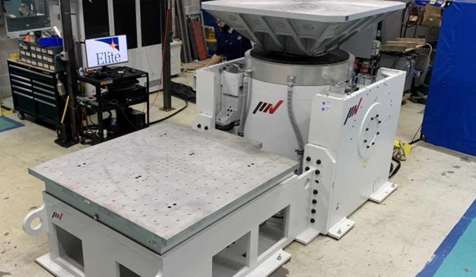


